Freezer to Refrigerator Conversion/Manufacturing Instructions: Difference between revisions
Jump to navigation
Jump to search
| (6 intermediate revisions by the same user not shown) | |||
| Line 22: | Line 22: | ||
==Step by Step== | ==Step by Step== | ||
<html> | |||
<br> | |||
<iframe src="https://docs.google.com/presentation/d/e/2PACX-1vR2FlD-lQ8ZONiGnbAQ1DyG-QC6hCpBQl2K5FPDCXH-s-u-wqxHyiNpmqhuDIzdhvBAz-O9QKO0yVVX/embed?start=true&loop=false&delayms=650" frameborder="0" width="480" height="299" allowfullscreen="true" mozallowfullscreen="true" webkitallowfullscreen="true"></iframe> | |||
</html> | |||
[https://docs.google.com/presentation/d/1gfTObmX4_pHFjR2LQuDlH-s5IGGih0JNTqnHl_JN3UI/edit edit] | |||
===1. drill holes=== | ===1. drill holes=== | ||
| Line 89: | Line 94: | ||
*solder female headers onto microcontroller if not pre-installed [https://learn.sparkfun.com/tutorials/how-to-solder-through-hole-soldering how to solder] | *solder female headers onto microcontroller if not pre-installed [https://learn.sparkfun.com/tutorials/how-to-solder-through-hole-soldering how to solder] | ||
*confirm that the arduino code has been uploaded | *confirm that the [[Freezer_to_Refrigerator_Conversion#Arduino_Code|arduino code]] has been uploaded [https://learn.adafruit.com/ladyadas-learn-arduino-lesson-number-1/upload-your-first-sketch how to upload] | ||
*review the microcontroller jumper connections on the wiring diagram | *review the microcontroller jumper connections on the wiring diagram | ||
**connect the usb cable | **connect the usb cable | ||
Latest revision as of 23:27, 17 July 2018
Safety Check
- Goggles
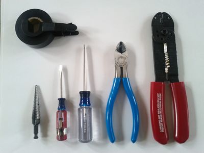
Tool Check
- drill
- stepped drill bit
- crimp tool
- wire cutter
- small blade screw driver
- phillips screw driver
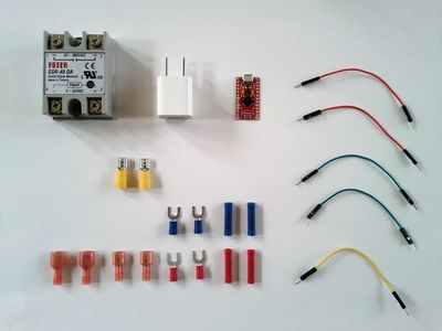
Inventory Check
See BOM
Step by Step
1. drill holes
- measure the diameter of the extension cord that will be used.
- using a stepped drill bit, cut two holes on opposite sides of the box.
- centered about 1"inch below edge of box
- drill a 5/32 hole for the thermister signal wire
2. place and cut wires
- cut extension cord for desired lengths. in half is fine.
- run about 8 inches of cord into holes.
- tie cord in a knot. pull knot firmly against the side of the box.
- strip off shielding, leaving about half an inch past knot.
3. fit check
- place the wall wart, relay switch and microcontroller into box.
- confirm that the usb cable can reach the microcontroller.
- using double sided stick strip, attach relay in place
- wrap electrical tape around male pins out of bottom of arduino if necesaary
4. crimp connections
- study the wiring harness diagram
- start with the AC extension cord wires.
- fit check the wires into place, then cut as needed.
- crimp ends as noted in diagram
- crimp green AC ground wires back togther
- cut thermister wire to length
- insert through its box hole
- tie knot inside box and pull tight against box wall
- crimp jumper wires as noted in diagram
- wrap resistor and adjoining connections in electrical tape
- fold back ends of thermister lead wires
- crimp each end into a fully insulated male connector
- wrap both connectors together with electrical tape
- wrap exposed lead wires from thermister leaving only the tip exposed
- crimp female connectors to thermister wire
5. install connections
- connect AC lines to relay screw terminals. look for the squigly line symbol (~).
- using a small blade screw driver, expand the yellow female connectors slightly
- slide yellow connectors on to the wall wart. polarity does not matter.
- connect the jumper wires with connector ends to the relay
- green wire to (-). red wire to (+).
- solder female headers onto microcontroller if not pre-installed how to solder
- confirm that the arduino code has been uploaded how to upload
- review the microcontroller jumper connections on the wiring diagram
- connect the usb cable
- connect the jumper wires as seen in the diagram
- then put the microcontroller in place in the box next to relay
6. test and finish
- connect an AC device to the plug (a wall clock is easy)
- plug into the wall
- confirm the microcontroller led is on
- confirm AC device is powered on
- place thermister into a freezer
- the AC power should turn off
- this verifies basic function
- feel free to tweak arduino code trigger values as desired
- screw on the PVC box's lid.
- install on chest freezer, you now have a chest refrigerator

