Angle Frame Connector: Difference between revisions
Jump to navigation
Jump to search
(→CAD) |
|||
| (5 intermediate revisions by the same user not shown) | |||
| Line 26: | Line 26: | ||
[https://docs.google.com/presentation/d/1IMkn4Z2OzDK-a8yy_De53_cd9d2_HGMtivGpcpdgdHw/edit edit] | [https://docs.google.com/presentation/d/1IMkn4Z2OzDK-a8yy_De53_cd9d2_HGMtivGpcpdgdHw/edit edit] | ||
[[File:Setscrew_mechanism.fcstd]] | |||
=Build= | |||
<html><iframe src="https://www.facebook.com/plugins/post.php?href=https%3A%2F%2Fwww.facebook.com%2Fmarcin.jakubowski.378%2Fposts%2F10218539045004527&show_text=true&width=552&height=400&appId" width="552" height="400" style="border:none;overflow:hidden" scrolling="no" frameborder="0" allowTransparency="true" allow="encrypted-media"></iframe></html> | |||
=Production= | =Production= | ||
==D3D Pro== | |||
*50% infill for real print. | *50% infill for real print. | ||
*Test print at 20%: 10 cm cut off the bottom, standing on corner - . This would not stand on moving-bed printers. Babystepping correction -0.75. It does not stand on a stationary bed printer eiether. I turned it around to print standing on 6 points. | *Test print at 20%: 10 cm cut off the bottom, standing on corner - . This would not stand on moving-bed printers. Babystepping correction -0.75. It does not stand on a stationary bed printer eiether. I turned it around to print standing on 6 points. | ||
| Line 40: | Line 46: | ||
[[File:cornerproductionengineering.png|500px]] | [[File:cornerproductionengineering.png|500px]] | ||
==D3D Simple== | |||
<html><iframe src="https://www.facebook.com/plugins/post.php?href=https%3A%2F%2Fwww.facebook.com%2Fmarcin.jakubowski.378%2Fposts%2F10217845988518548&width=500" width="500" height="378" style="border:none;overflow:hidden" scrolling="no" frameborder="0" allowTransparency="true" allow="encrypted-media"></iframe></html> | |||
Printer profile - [[File:d3duniversal_7.ini]] - 100%, see support parameters. | |||
Support parameters: | |||
[[File:supportparameters.png|500px]] | |||
Results: | |||
#100% infill - no way. Not enough stick to bed, starts warping after excellent first layer. | |||
#100% infill - roughed up surface with sand paper, 8 line brim. No way. Still comes right off. | |||
#Painter's tape - reduce infill to 20% for a less solid part but still bootstrappable to D3D Pro. | |||
Latest revision as of 18:01, 6 July 2020
Build

CAD


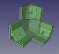
Angle Connector. - FreeCAD with McMaster 6 mm nut -File:Angleconnector.fcstd. Finished STL - File:Anglecorner.stl
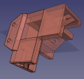
Angle Connector with axis mount, left side. - FreeCAD - File:Leftcorner.fcstd. Finished STL - File:Leftcorner.stl
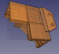
Angle Connector with axis mount, right side. - FreeCAD - File:Rightcorner.fcstd. Finished STL - File:Rightcorner.stl
Concept
Build
Production
D3D Pro
- 50% infill for real print.
- Test print at 20%: 10 cm cut off the bottom, standing on corner - . This would not stand on moving-bed printers. Babystepping correction -0.75. It does not stand on a stationary bed printer eiether. I turned it around to print standing on 6 points.

- Came off bed so printed it on 6 corners:
- Initial fit: metal shown with 6 mm hex nut and set screw in the hole.
- STL - sunk 5 mm into bed. Test print at 20%, takes 8.5 hrs. Production print: 50% infill, 10:10 hours, 133 g. Brim 10 lines. Prints starting on 6 corners, for a solid base.

D3D Simple
Printer profile - File:D3duniversal 7.ini - 100%, see support parameters.
Support parameters:

Results:
- 100% infill - no way. Not enough stick to bed, starts warping after excellent first layer.
- 100% infill - roughed up surface with sand paper, 8 line brim. No way. Still comes right off.
- Painter's tape - reduce infill to 20% for a less solid part but still bootstrappable to D3D Pro.