PVC Pipe and Fittings Library: Difference between revisions
| (123 intermediate revisions by 4 users not shown) | |||
| Line 1: | Line 1: | ||
= | =Basics= | ||
This is a library of all the current PVC Pipe and Fittings that have been made in freecad for OSE. Many fittings can be created using [[OSE Piping Workbench]]. | |||
= Pipe dimensions used in literature = | |||
* O.D. - outer diameter. | |||
* Average I.D. - average inner diameter (why average?). This dimension determines the size of the pipe. | |||
* Min. Wall - thickness of the pipe wall. | |||
* Schedule - determines (indirectly) the thickness of the wall. | |||
=Basic Parts= | |||
*1.5" elbow - | |||
*2" coupler - [[File:2inchcoupler.fcstd]] | |||
=Parts Generated Using the OSE Piping Workbench + Other= | |||
= | <gallery perrow=6> | ||
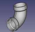
File:3elbow.png |'''3" PVC Elbow'''. Standard height of 4.75" as in [https://www.mcmaster.com/2389K29/]. - size:20kb - FreeCAD -[[File:3"-pvc-elbow.fcstd]], | |||
[[File: | |||
File:toiletparts.png| '''Toilet Parts''' - Includes closet flange, 3" elbow with 2" heel, long 3" elbow - [[File:toiletparts.fcstd]] | |||
[[File: | File:rotatabletrap.png |'''1.5" rotatable trap''' - FreeCAD -[[File:15rottrap.fcstd]] | ||
[[File: | File:2doublesanteetee.png |'''2" sanitary tee''' - FreeCAD -[[File:2doublesantee.fcstd]] | ||
File:2doublefixtee.png |'''2" double fixture tee''' - Nibco site - [https://catalog.nibco.com/rfcconfirmation?name=all-categories&xcartid=27675] FreeCAD -[[File:2doublefixtee.fcstd]] | |||
[[File: | |||
File:3to15bushing.png |'''3" to 1.5" reducer bushing''' - FreeCAD -[[File:3to15bushing.fcstd]] | |||
File:3wye.png |'''3" wye''' - size:80kb - FreeCAD -[[File:3wye.fcstd]] | |||
File:345streetbend.png |'''3" 45 degree street elbow''' - size:80kb - FreeCAD -[[File:345streetbend.fcstd]] | |||
File:1FKHDAF.png|'''1.5" 45 degree street elbow''' - size:80kb - FreeCAD -[[File:1545streetbend.fcstd]] | |||
File:15elbow.png |'''1.5" elbow''' - size:30kb - FreeCAD -[[File:15elbow.fcstd]] | |||
File: | |||
File:2tee.png |'''2 inch tee''' - size: 25k - FreeCAD -[[File:2tee.fcstd]] | |||
File:create-pipe-cad-screenshot.png |'''SCH40 1" PVC pipe''' - size:5kb - FreeCAD -[[File:pipe-test.fcstd]], | |||
File:create-elbow-cad-screenshot.png |'''Elbow test file.''' Here alpha° is 45°. - size:21kb - FreeCAD -[[File:elbow-test.fcstd]], | |||
File:create-coupling-cad-screenshot.png |'''1"-1/2" coupling test file''' - size:17kb - FreeCAD -[[File:coupling-test.fcstd]] | |||
File:create-bushing-cad-screenshot.png |'''1"-1/2" bushing''' - size:21kb - FreeCAD -[[File:bushing-test.fcstd]] | |||
File:create-tee-cad-screenshot.png |'''1" tee test file''' - size:28kb - FreeCAD -[[File:tee-test.fcstd]] | |||
File:create-cross-cad-screenshot.png |'''1" cross test file''' - size:34kb - FreeCAD -[[File:cross-test.fcstd]] | |||
File:create-corner-cad-screenshot.png |'''1" outer corner test file''' - size:30kb - FreeCAD -[[File:corner-test.fcstd]] | |||
</gallery> | </gallery> | ||
=Library of STEP Downloads from McMaster Carr= | =Library of STEP Downloads from McMaster Carr= | ||
Comparable in size to generated parts - except for some parts which are way too heavy. | Comparable in size to generated parts - except for some parts which are way too heavy. | ||
<gallery perrow=6> | <gallery perrow=6> | ||
File:elbow.png |'''1" PVC Elbow''' - size:19kb - FreeCAD -[[File:1"-pvc-elbow.fcstd]], | File:elbow.png |'''1" PVC Elbow''' - size:19kb - FreeCAD -[[File:1"-pvc-elbow.fcstd]], | ||
| Line 117: | Line 63: | ||
File:1"-pvc-valve.jpg |'''1" PVC Valve''' - size:500kb - FreeCAD -[[File:1"-pvc-valve.fcstd]], | File:1"-pvc-valve.jpg |'''1" PVC Valve''' - size:500kb - FreeCAD -[[File:1"-pvc-valve.fcstd]], | ||
File:1"-34"-reducer.jpg |'''1"-3/4" PVC | File:1"-34"-reducer.jpg |'''1"-3/4" PVC Bushing''' - size:13kb - FreeCAD -[[File:1"-34"-reducer.fcstd]], | ||
File:1"-cross.jpg |'''1" PVC Cross''' - size:13kb - FreeCAD -[[File:1"-cross.fcstd]], | File:1"-cross.jpg |'''1" PVC Cross''' - size:13kb - FreeCAD -[[File:1"-cross.fcstd]], | ||
File:2"-elbow.jpg |'''2" PVC Elbow''' - size:157kb - FreeCAD -[[File:2"-elbow.fcstd]], | |||
= | File:2"-tee.png |'''2" PVC Tee''' -157k - STEP -[https://www.mcmaster.com/#2389k23/=1bcgk5c] - FreeCAD - [[File:2"-pvc-tee.fcstd]] | ||
File:2"-elbow-short.png |'''2" PVC Elbow - Short Nonstandard''' - size:4kb - STEP -[https://www.mcmaster.com/#4881k26/=1bcheo0] - FreeCAD - [[File:2"-pvc-tee-short.fcstd]] (file misnamed) | |||
[https:// | |||
File:2"-3"-bushing.jpg |'''2"-3" bushing''' - size:161kb - STEP -[https://www.mcmaster.com/#2389k53/=1bchs2a] - FreeCAD - [[File:2"-3"-bushing.fcstd]] | |||
File:3"-2"-reducer.jpg |'''2"-3" reducer. Note difference between a reducer and a bushing (last one)''' - size:161kb - Menards -[https://www.menards.com/main/plumbing/rough-plumbing/pipe-tubing-hoses-fittings-accessories/fittings/pvc-fittings/nibco-reg-3x2-reducing-pvc-coupling-dwv/p-1444449202566-c-8557.htm?tid=-6388088944482732916&ipos=4] - FreeCAD - [[File:3"-2"-reducer.fcstd]] | |||
File:3"-2"-reducer.jpg |'''2"-1" reducer.''' - size:10kb - STEP -[https://www.mcmaster.com/#4880k338/=1bemizt] - FreeCAD - [[File:2"-1"-PVC-reducer.fcstd]] | |||
</gallery> | |||
= FAQ = | |||
* Do we really want to 3D-print pipe fittings? Somehow I have doubt about mechanical properties of the 3D-printed products. | * Do we really want to 3D-print pipe fittings? Somehow I have doubt about mechanical properties of the 3D-printed products. | ||
*: Yes. For high pressure applications - 300 PSI - we would have to be very careful. For low pressure, such as 5 PSI, it's not a problem. Eventually, we want to refine printing techniques where our fittings can do what standard schedule 80 ABS fittings can do. | *: Yes. For high pressure applications - 300 PSI - we would have to be very careful. For low pressure, such as 5 PSI, it's not a problem. Eventually, we want to refine printing techniques where our fittings can do what standard schedule 80 ABS fittings can do. | ||
** Also with things such as part baking/[[FDM 3D Print Annealing | annealing]], composite filaments, and SLA or SLS Printers, very durable parts can be made. Granted i agree proper testing, and potentially getting "Listed" or whatever the [[Building Code]] / [[Insurance]] stuff would need | |||
[[Category: Materials]] [[Category: Plumbing]] | |||
Latest revision as of 19:16, 25 August 2023
Basics
This is a library of all the current PVC Pipe and Fittings that have been made in freecad for OSE. Many fittings can be created using OSE Piping Workbench.
Pipe dimensions used in literature
- O.D. - outer diameter.
- Average I.D. - average inner diameter (why average?). This dimension determines the size of the pipe.
- Min. Wall - thickness of the pipe wall.
- Schedule - determines (indirectly) the thickness of the wall.
Basic Parts
- 1.5" elbow -
- 2" coupler - File:2inchcoupler.fcstd
Parts Generated Using the OSE Piping Workbench + Other
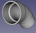
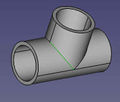
![3" PVC Elbow. Standard height of 4.75" as in [1]. - size:20kb - FreeCAD -File:3"-pvc-elbow.fcstd,](/images/thumb/0/04/3elbow.png/120px-3elbow.png)
3" PVC Elbow. Standard height of 4.75" as in [1]. - size:20kb - FreeCAD -File:3"-pvc-elbow.fcstd,
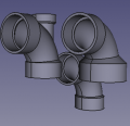
Toilet Parts - Includes closet flange, 3" elbow with 2" heel, long 3" elbow - File:Toiletparts.fcstd

1.5" rotatable trap - FreeCAD -File:15rottrap.fcstd
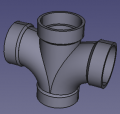
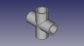
2" sanitary tee - FreeCAD -File:2doublesantee.fcstd
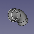
![2" double fixture tee - Nibco site - [2] FreeCAD -File:2doublefixtee.fcstd](/images/thumb/c/c4/2doublefixtee.png/120px-2doublefixtee.png)
2" double fixture tee - Nibco site - [2] FreeCAD -File:2doublefixtee.fcstd
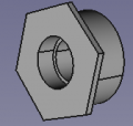
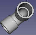
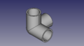
3" to 1.5" reducer bushing - FreeCAD -File:3to15bushing.fcstd
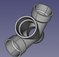
3" wye - size:80kb - FreeCAD -File:3wye.fcstd
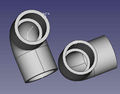
3" 45 degree street elbow - size:80kb - FreeCAD -File:345streetbend.fcstd
1.5" 45 degree street elbow - size:80kb - FreeCAD -File:1545streetbend.fcstd
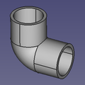
1.5" elbow - size:30kb - FreeCAD -File:15elbow.fcstd
- 2tee.png
2 inch tee - size: 25k - FreeCAD -File:2tee.fcstd
SCH40 1" PVC pipe - size:5kb - FreeCAD -File:Pipe-test.fcstd,
Elbow test file. Here alpha° is 45°. - size:21kb - FreeCAD -File:Elbow-test.fcstd,
1"-1/2" coupling test file - size:17kb - FreeCAD -File:Coupling-test.fcstd
1"-1/2" bushing - size:21kb - FreeCAD -File:Bushing-test.fcstd
1" tee test file - size:28kb - FreeCAD -File:Tee-test.fcstd
1" cross test file - size:34kb - FreeCAD -File:Cross-test.fcstd
1" outer corner test file - size:30kb - FreeCAD -File:Corner-test.fcstd
![3" PVC Elbow. Standard height of 4.75" as in [1]. - size:20kb - FreeCAD -File:3"-pvc-elbow.fcstd,](/wiki/File:3elbow.png)


![2" double fixture tee - Nibco site - [2] FreeCAD -File:2doublefixtee.fcstd](/wiki/File:2doublefixtee.png)


Library of STEP Downloads from McMaster Carr
Comparable in size to generated parts - except for some parts which are way too heavy.
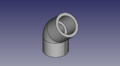
1" PVC Elbow - size:19kb - FreeCAD -File:1"-pvc-elbow.fcstd,
Note slight difference compared to generated - 0.15" wall for generated, 0.12 for downloaded.
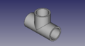
1" PVC Tee - size:25kb - FreeCAD -File:1"-pvc-tee.fcstd,
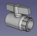
1" PVC Valve - size:500kb - FreeCAD -File:1"-pvc-valve.fcstd,
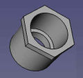
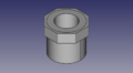
1"-3/4" PVC Bushing - size:13kb - FreeCAD -File:1"-34"-reducer.fcstd,
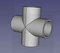
1" PVC Cross - size:13kb - FreeCAD -File:1"-cross.fcstd,
2" PVC Elbow - size:157kb - FreeCAD -File:2"-elbow.fcstd,
![2" PVC Tee -157k - STEP -[3] - FreeCAD - File:2"-pvc-tee.fcstd](/images/thumb/8/8d/2%22-tee.png/119px-2%22-tee.png)
2" PVC Tee -157k - STEP -[3] - FreeCAD - File:2"-pvc-tee.fcstd
![2" PVC Elbow - Short Nonstandard - size:4kb - STEP -[4] - FreeCAD - File:2"-pvc-tee-short.fcstd (file misnamed)](/images/thumb/4/4d/2%22-elbow-short.png/120px-2%22-elbow-short.png)
2" PVC Elbow - Short Nonstandard - size:4kb - STEP -[4] - FreeCAD - File:2"-pvc-tee-short.fcstd (file misnamed)
- 2"-3"-bushing.jpg
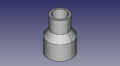
2"-3" bushing - size:161kb - STEP -[5] - FreeCAD - File:2"-3"-bushing.fcstd
- 3"-2"-reducer.jpg
2"-3" reducer. Note difference between a reducer and a bushing (last one) - size:161kb - Menards -[6] - FreeCAD - File:3"-2"-reducer.fcstd
- 3"-2"-reducer.jpg
2"-1" reducer. - size:10kb - STEP -[7] - FreeCAD - File:2"-1"-PVC-reducer.fcstd


![2" PVC Tee -157k - STEP -[3] - FreeCAD - File:2"-pvc-tee.fcstd](/wiki/File:2%22-tee.png)
![2" PVC Elbow - Short Nonstandard - size:4kb - STEP -[4] - FreeCAD - File:2"-pvc-tee-short.fcstd (file misnamed)](/wiki/File:2%22-elbow-short.png)
FAQ
- Do we really want to 3D-print pipe fittings? Somehow I have doubt about mechanical properties of the 3D-printed products.
- Yes. For high pressure applications - 300 PSI - we would have to be very careful. For low pressure, such as 5 PSI, it's not a problem. Eventually, we want to refine printing techniques where our fittings can do what standard schedule 80 ABS fittings can do.
- Also with things such as part baking/ annealing, composite filaments, and SLA or SLS Printers, very durable parts can be made. Granted i agree proper testing, and potentially getting "Listed" or whatever the Building Code / Insurance stuff would need