PVC Pipe and Fittings Library: Difference between revisions
No edit summary |
(→Basics) |
||
| (184 intermediate revisions by 4 users not shown) | |||
| Line 1: | Line 1: | ||
= | =Basics= | ||
This is a library of all the current PVC Pipe and Fittings that have been made in freecad for OSE. Many fittings can be created using [[OSE Piping Workbench]]. | |||
=Seed Eco-Home 6= | |||
*Plumbing file - [https://drive.google.com/drive/folders/1FtcP-Ljy2xHXry87OtCxtl8WBE7or4A3] | |||
= Pipe dimensions used in literature = | |||
* O.D. - outer diameter. | |||
* Average I.D. - average inner diameter (why average?). This dimension determines the size of the pipe. | |||
* Min. Wall - thickness of the pipe wall. | |||
* Schedule - determines (indirectly) the thickness of the wall. | |||
= | =Basic Parts= | ||
*1.5" elbow - | |||
*2" coupler - [[File:2inchcoupler.fcstd]] | |||
=Parts Generated Using the OSE Piping Workbench + Other= | |||
= | <gallery perrow=6> | ||
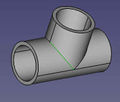
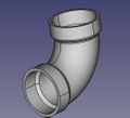
File:3elbow.png |'''3" PVC Elbow'''. Standard height of 4.75" as in [https://www.mcmaster.com/2389K29/]. - size:20kb - FreeCAD -[[File:3"-pvc-elbow.fcstd]], | |||
File:toiletparts.png| '''Toilet Parts''' - Includes closet flange, 3" elbow with 2" heel, long 3" elbow - [[File:toiletparts.fcstd]] | |||
File:rotatabletrap.png |'''1.5" rotatable trap''' - FreeCAD -[[File:15rottrap.fcstd]] | |||
= | File:2doublesanteetee.png |'''2" sanitary tee''' - FreeCAD -[[File:2doublesantee.fcstd]] | ||
File:2doublefixtee.png |'''2" double fixture tee''' - Nibco site - [https://catalog.nibco.com/rfcconfirmation?name=all-categories&xcartid=27675] FreeCAD -[[File:2doublefixtee.fcstd]] | |||
File:3to15bushing.png |'''3" to 1.5" reducer bushing''' - FreeCAD -[[File:3to15bushing.fcstd]] | |||
File:3wye.png |'''3" wye''' - size:80kb - FreeCAD -[[File:3wye.fcstd]] | |||
File:345streetbend.png |'''3" 45 degree street elbow''' - size:80kb - FreeCAD -[[File:345streetbend.fcstd]] | |||
File:1FKHDAF.png|'''1.5" 45 degree street elbow''' - size:80kb - FreeCAD -[[File:1545streetbend.fcstd]] | |||
File:15elbow.png |'''1.5" elbow''' - size:30kb - FreeCAD -[[File:15elbow.fcstd]] | |||
File:2tee.png |'''2 inch tee''' - size: 25k - FreeCAD -[[File:2tee.fcstd]] | |||
File:create-pipe-cad-screenshot.png |'''SCH40 1" PVC pipe''' - size:5kb - FreeCAD -[[File:pipe-test.fcstd]], | |||
File:create-elbow-cad-screenshot.png |'''Elbow test file.''' Here alpha° is 45°. - size:21kb - FreeCAD -[[File:elbow-test.fcstd]], | |||
File:create-coupling-cad-screenshot.png |'''1"-1/2" coupling test file''' - size:17kb - FreeCAD -[[File:coupling-test.fcstd]] | |||
File:create-bushing-cad-screenshot.png |'''1"-1/2" bushing''' - size:21kb - FreeCAD -[[File:bushing-test.fcstd]] | |||
File:create-tee-cad-screenshot.png |'''1" tee test file''' - size:28kb - FreeCAD -[[File:tee-test.fcstd]] | |||
File:create-cross-cad-screenshot.png |'''1" cross test file''' - size:34kb - FreeCAD -[[File:cross-test.fcstd]] | |||
File:create-corner-cad-screenshot.png |'''1" outer corner test file''' - size:30kb - FreeCAD -[[File:corner-test.fcstd]] | |||
</gallery> | |||
= | =Library of STEP Downloads from McMaster Carr= | ||
Comparable in size to generated parts - except for some parts which are way too heavy. | |||
<gallery perrow=6> | <gallery perrow=6> | ||
[[File:pvc- | File:elbow.png |'''1" PVC Elbow''' - size:19kb - FreeCAD -[[File:1"-pvc-elbow.fcstd]], | ||
File:elbowcomp.jpg |Note slight difference compared to generated - 0.15" wall for generated, 0.12 for downloaded. | |||
File:1"-pvc-tee.jpg |'''1" PVC Tee''' - size:25kb - FreeCAD -[[File:1"-pvc-tee.fcstd]], | |||
File:1"-pvc-valve.jpg |'''1" PVC Valve''' - size:500kb - FreeCAD -[[File:1"-pvc-valve.fcstd]], | |||
File:1"-34"-reducer.jpg |'''1"-3/4" PVC Bushing''' - size:13kb - FreeCAD -[[File:1"-34"-reducer.fcstd]], | |||
File:1"-cross.jpg |'''1" PVC Cross''' - size:13kb - FreeCAD -[[File:1"-cross.fcstd]], | |||
File:2"-elbow.jpg |'''2" PVC Elbow''' - size:157kb - FreeCAD -[[File:2"-elbow.fcstd]], | |||
File:2"-tee.png |'''2" PVC Tee''' -157k - STEP -[https://www.mcmaster.com/#2389k23/=1bcgk5c] - FreeCAD - [[File:2"-pvc-tee.fcstd]] | |||
File:2"-elbow-short.png |'''2" PVC Elbow - Short Nonstandard''' - size:4kb - STEP -[https://www.mcmaster.com/#4881k26/=1bcheo0] - FreeCAD - [[File:2"-pvc-tee-short.fcstd]] (file misnamed) | |||
= | File:2"-3"-bushing.jpg |'''2"-3" bushing''' - size:161kb - STEP -[https://www.mcmaster.com/#2389k53/=1bchs2a] - FreeCAD - [[File:2"-3"-bushing.fcstd]] | ||
[[File: | File:3"-2"-reducer.jpg |'''2"-3" reducer. Note difference between a reducer and a bushing (last one)''' - size:161kb - Menards -[https://www.menards.com/main/plumbing/rough-plumbing/pipe-tubing-hoses-fittings-accessories/fittings/pvc-fittings/nibco-reg-3x2-reducing-pvc-coupling-dwv/p-1444449202566-c-8557.htm?tid=-6388088944482732916&ipos=4] - FreeCAD - [[File:3"-2"-reducer.fcstd]] | ||
File:3"-2"-reducer.jpg |'''2"-1" reducer.''' - size:10kb - STEP -[https://www.mcmaster.com/#4880k338/=1bemizt] - FreeCAD - [[File:2"-1"-PVC-reducer.fcstd]] | |||
</gallery> | |||
= FAQ = | |||
* Do we really want to 3D-print pipe fittings? Somehow I have doubt about mechanical properties of the 3D-printed products. | |||
*: Yes. For high pressure applications - 300 PSI - we would have to be very careful. For low pressure, such as 5 PSI, it's not a problem. Eventually, we want to refine printing techniques where our fittings can do what standard schedule 80 ABS fittings can do. | |||
** Also with things such as part baking/[[FDM 3D Print Annealing | annealing]], composite filaments, and SLA or SLS Printers, very durable parts can be made. Granted i agree proper testing, and potentially getting "Listed" or whatever the [[Building Code]] / [[Insurance]] stuff would need | |||
[[Category: Materials]] [[Category: Plumbing]] | |||
Latest revision as of 04:39, 8 September 2025
Basics
This is a library of all the current PVC Pipe and Fittings that have been made in freecad for OSE. Many fittings can be created using OSE Piping Workbench.
Seed Eco-Home 6
- Plumbing file - [8]
Pipe dimensions used in literature
- O.D. - outer diameter.
- Average I.D. - average inner diameter (why average?). This dimension determines the size of the pipe.
- Min. Wall - thickness of the pipe wall.
- Schedule - determines (indirectly) the thickness of the wall.
Basic Parts
- 1.5" elbow -
- 2" coupler - File:2inchcoupler.fcstd
Parts Generated Using the OSE Piping Workbench + Other
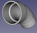
![3" PVC Elbow. Standard height of 4.75" as in [1]. - size:20kb - FreeCAD -File:3"-pvc-elbow.fcstd,](/images/thumb/0/04/3elbow.png/120px-3elbow.png)
3" PVC Elbow. Standard height of 4.75" as in [1]. - size:20kb - FreeCAD -File:3"-pvc-elbow.fcstd,
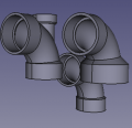
Toilet Parts - Includes closet flange, 3" elbow with 2" heel, long 3" elbow - File:Toiletparts.fcstd

1.5" rotatable trap - FreeCAD -File:15rottrap.fcstd
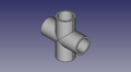
2" sanitary tee - FreeCAD -File:2doublesantee.fcstd
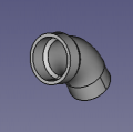
![2" double fixture tee - Nibco site - [2] FreeCAD -File:2doublefixtee.fcstd](/images/thumb/c/c4/2doublefixtee.png/120px-2doublefixtee.png)
2" double fixture tee - Nibco site - [2] FreeCAD -File:2doublefixtee.fcstd
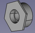
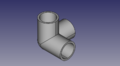
3" to 1.5" reducer bushing - FreeCAD -File:3to15bushing.fcstd
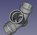
3" wye - size:80kb - FreeCAD -File:3wye.fcstd
3" 45 degree street elbow - size:80kb - FreeCAD -File:345streetbend.fcstd
1.5" 45 degree street elbow - size:80kb - FreeCAD -File:1545streetbend.fcstd
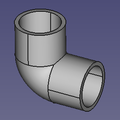
1.5" elbow - size:30kb - FreeCAD -File:15elbow.fcstd
- 2tee.png
2 inch tee - size: 25k - FreeCAD -File:2tee.fcstd
SCH40 1" PVC pipe - size:5kb - FreeCAD -File:Pipe-test.fcstd,
Elbow test file. Here alpha° is 45°. - size:21kb - FreeCAD -File:Elbow-test.fcstd,
1"-1/2" coupling test file - size:17kb - FreeCAD -File:Coupling-test.fcstd
1"-1/2" bushing - size:21kb - FreeCAD -File:Bushing-test.fcstd
1" tee test file - size:28kb - FreeCAD -File:Tee-test.fcstd
1" cross test file - size:34kb - FreeCAD -File:Cross-test.fcstd
1" outer corner test file - size:30kb - FreeCAD -File:Corner-test.fcstd
![3" PVC Elbow. Standard height of 4.75" as in [1]. - size:20kb - FreeCAD -File:3"-pvc-elbow.fcstd,](/wiki/File:3elbow.png)


![2" double fixture tee - Nibco site - [2] FreeCAD -File:2doublefixtee.fcstd](/wiki/File:2doublefixtee.png)


Library of STEP Downloads from McMaster Carr
Comparable in size to generated parts - except for some parts which are way too heavy.
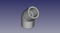
1" PVC Elbow - size:19kb - FreeCAD -File:1"-pvc-elbow.fcstd,
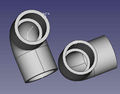
Note slight difference compared to generated - 0.15" wall for generated, 0.12 for downloaded.
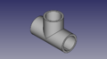
1" PVC Tee - size:25kb - FreeCAD -File:1"-pvc-tee.fcstd,
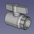
1" PVC Valve - size:500kb - FreeCAD -File:1"-pvc-valve.fcstd,
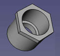
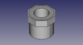
1"-3/4" PVC Bushing - size:13kb - FreeCAD -File:1"-34"-reducer.fcstd,
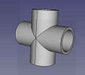
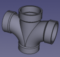
1" PVC Cross - size:13kb - FreeCAD -File:1"-cross.fcstd,
2" PVC Elbow - size:157kb - FreeCAD -File:2"-elbow.fcstd,
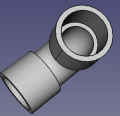
![2" PVC Tee -157k - STEP -[3] - FreeCAD - File:2"-pvc-tee.fcstd](/images/thumb/8/8d/2%22-tee.png/119px-2%22-tee.png)
2" PVC Tee -157k - STEP -[3] - FreeCAD - File:2"-pvc-tee.fcstd
![2" PVC Elbow - Short Nonstandard - size:4kb - STEP -[4] - FreeCAD - File:2"-pvc-tee-short.fcstd (file misnamed)](/images/thumb/4/4d/2%22-elbow-short.png/120px-2%22-elbow-short.png)
2" PVC Elbow - Short Nonstandard - size:4kb - STEP -[4] - FreeCAD - File:2"-pvc-tee-short.fcstd (file misnamed)
- 2"-3"-bushing.jpg
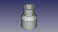
2"-3" bushing - size:161kb - STEP -[5] - FreeCAD - File:2"-3"-bushing.fcstd
- 3"-2"-reducer.jpg
2"-3" reducer. Note difference between a reducer and a bushing (last one) - size:161kb - Menards -[6] - FreeCAD - File:3"-2"-reducer.fcstd
- 3"-2"-reducer.jpg
2"-1" reducer. - size:10kb - STEP -[7] - FreeCAD - File:2"-1"-PVC-reducer.fcstd


![2" PVC Tee -157k - STEP -[3] - FreeCAD - File:2"-pvc-tee.fcstd](/wiki/File:2%22-tee.png)
![2" PVC Elbow - Short Nonstandard - size:4kb - STEP -[4] - FreeCAD - File:2"-pvc-tee-short.fcstd (file misnamed)](/wiki/File:2%22-elbow-short.png)
FAQ
- Do we really want to 3D-print pipe fittings? Somehow I have doubt about mechanical properties of the 3D-printed products.
- Yes. For high pressure applications - 300 PSI - we would have to be very careful. For low pressure, such as 5 PSI, it's not a problem. Eventually, we want to refine printing techniques where our fittings can do what standard schedule 80 ABS fittings can do.
- Also with things such as part baking/ annealing, composite filaments, and SLA or SLS Printers, very durable parts can be made. Granted i agree proper testing, and potentially getting "Listed" or whatever the Building Code / Insurance stuff would need