Inverter SEBD: Difference between revisions
No edit summary |
m (+Category:Electronics) |
||
| (3 intermediate revisions by one other user not shown) | |||
| Line 10: | Line 10: | ||
The power produced by inverters is usually one of two types: | The power produced by inverters is usually one of two types: | ||
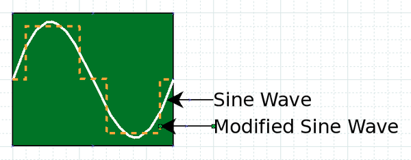
'''Modified Sine Wave''' - Similar to sine wave, but waveform is rectangular rather than rounded. While the simpler design of these inverters are less expensive many devices will not work properly with power using a modified sine wave, such as televisions and computers. | |||
'''Pure Sine Wave''' - Accurately simulates the sine wave power. They are usually employ more complicated circuitry and are more expensive. They can be used with any common AC device. The following diagram shows both sine and modified sine waves: | |||
[[Image:waveform.png|600px]] | [[Image:waveform.png|600px]] | ||
| Line 24: | Line 24: | ||
Inverter designs typically employ the following elements: | Inverter designs typically employ the following elements: | ||
'''Oscillator''' - Provides a reference waveform for comparing the output waveform and creating feedback. | |||
Driver circuit - Outputs signals to "drive" the output amplifier to switch the DC power on and off. The driver circuit must employ feedback from the final output for comparing to the waveform from the oscillator. Feedback can also be used to adjust for excessive power demand. The driver circuit should be split into two parts for driving both positive and negative components of the waveform. | Driver circuit - Outputs signals to "drive" the output amplifier to switch the DC power on and off. The driver circuit must employ feedback from the final output for comparing to the waveform from the oscillator. Feedback can also be used to adjust for excessive power demand. The driver circuit should be split into two parts for driving both positive and negative components of the waveform. | ||
'''Output Amplifier''' - These high-power electronic devices switch the DC power into rectangular waveforms which then go to the transformer. | |||
'''Transformer''' - Transformers typically employ two sets of windings to transform the input:output voltages according to the number of windings in each coil. In addition, transformers are inductors, which provide some "smoothing" of waveform irregularities. | |||
Concept diagram: | Concept diagram: | ||
[[Image: | [[Image:inverterconcept3.png|600px]] | ||
[[Category:Electronics]] | |||
Latest revision as of 05:04, 21 December 2011
Introduction
Inverters convert DC electricity into AC electricity. Many different types of inverters are available as they vary in power, efficiency and function. Inverters are typically used to draw power from one or more 12 V batteries and convert it into 120 V AC at 60 Hz - for use in ordinary household outlets.
Design Considerations
The power produced by inverters is usually one of two types:
Modified Sine Wave - Similar to sine wave, but waveform is rectangular rather than rounded. While the simpler design of these inverters are less expensive many devices will not work properly with power using a modified sine wave, such as televisions and computers.
Pure Sine Wave - Accurately simulates the sine wave power. They are usually employ more complicated circuitry and are more expensive. They can be used with any common AC device. The following diagram shows both sine and modified sine waves:
Inverter designs commonly have "throttling" logic that shuts down the inverter in case demand exceeds design limits. Another common feature is to shut down the output in case of excessive temperature.
Inverter Design
Inverter designs typically employ the following elements:
Oscillator - Provides a reference waveform for comparing the output waveform and creating feedback.
Driver circuit - Outputs signals to "drive" the output amplifier to switch the DC power on and off. The driver circuit must employ feedback from the final output for comparing to the waveform from the oscillator. Feedback can also be used to adjust for excessive power demand. The driver circuit should be split into two parts for driving both positive and negative components of the waveform.
Output Amplifier - These high-power electronic devices switch the DC power into rectangular waveforms which then go to the transformer.
Transformer - Transformers typically employ two sets of windings to transform the input:output voltages according to the number of windings in each coil. In addition, transformers are inductors, which provide some "smoothing" of waveform irregularities.
Concept diagram:

