Tobbens Adding Inductive Proximity Sensor Log: Difference between revisions
(→Theory) |
No edit summary |
||
| Line 21: | Line 21: | ||
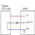
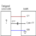
The diode stops current to flowing into the Z_min pin with harmful 12 V pressure, but allows the pullup voltage of 5V to flow down to ground. | The diode stops current to flowing into the Z_min pin with harmful 12 V pressure, but allows the pullup voltage of 5V to flow down to ground. | ||
= Implementation = | |||
I'll be using an IN4004, MIC salvaged from another RAMPS board. | |||
<gallery widths=300px, heights=250px> | |||
Salvaged_diode.JPG | |||
Zip_tie_engineering.JPG | |||
</gallery> | |||
Feed 12 V directly from power supply. | |||
Updated Marlin in [https://github.com/tobbelobb/D3D_Folgertech_Prusai3_Marlin repo] to auto bed compensate. | |||
Posted [https://youtu.be/sGCFfd9jnao video] of it all working... | |||
Revision as of 15:44, 6 March 2016
Introduction
This page documents adding a Research_On_Inductive_Proximity_Sensors#LJ12A3-4-Z.2FBX LJ12A3-4-Z/BX inductive proximity sensor to a Folgertech 2020 Prusa i3. Printer assembly up until this point is documented in Tobbens_Folgertech_Kit_Unboxing_Log and Tobbens_Folgertech_Kit_Assembly_Log. Not documented there is only the addition of an aluminum plate on top of the heat bed, like shown in the pictures below:
Theory
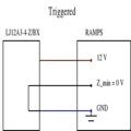
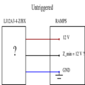
The sensor if of NPN type and normally open. It is not drivable with 5 V, so we will feed it with 12 V. We expect the following two states if we wire it in directly:
The Z_min pin is part of the RAMPS' logical circuitry and will be damaged if it is exposed to 12 V, so we need to protect it. For that, we use a diode and internal Z_min pullup:
The diode stops current to flowing into the Z_min pin with harmful 12 V pressure, but allows the pullup voltage of 5V to flow down to ground.
Implementation
I'll be using an IN4004, MIC salvaged from another RAMPS board.
Feed 12 V directly from power supply.
Updated Marlin in repo to auto bed compensate.
Posted video of it all working...


