Tobbens Adding Inductive Proximity Sensor Log
Introduction
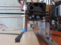
This page documents adding a Research_On_Inductive_Proximity_Sensors#LJ12A3-4-Z.2FBX LJ12A3-4-Z/BX inductive proximity sensor to a Folgertech 2020 Prusa i3. Printer assembly up until this point is documented in Tobbens_Folgertech_Kit_Unboxing_Log and Tobbens_Folgertech_Kit_Assembly_Log. Not documented there is only the addition of an aluminum plate on top of the heat bed, like shown in the pictures on the right hand side.


Update: it appears the aluminum plate is not needed, as the sensor triggers on the heat bed. 3/7/16
Data
Repeatability at Constant Temperature
It is useful do document the repeatability of the sensor. +/1 0.1 mm repeatability would be the minimum requirement for 200 micron layer heights. Data on repeatability for 10 consecutive probes:
1.644000 mm
1.648000 mm
1.664500 mm
1.663000 mm
1.641000 mm
1.664500 mm
1.673000 mm
1.649000 mm
1.664250 mm
1.660500 mm
--------
Standard Deviation: 0.010193 mm
Highest value - Lowest value: 0.032000 mm
The above data was collected by issuing the following commands to Marlin
G28
M48 P1 V2
The closest the M48 command gets to being documented is this forum thread and a comment in the Marlin source code.
Repeatability at Changing Temperature
This section contains only one data-point for now. Procedure was the following:
- Locate sensor above middle of print bed
- Note print bed temperature (22.5 C) and hot end temperature (21.1 C)
- Lower sensor in increments of 0.01 mm until sensor triggers
- Note down the z-height (1.13 mm)
- Heat print bed to 100 C and print head to 200 C
- Raise sensor until it is un-triggered and lower it in increments of 0.01 until it re-triggers.
- Note down the new z-height (2.76 mm)
From the measured numbers we see that heating the heater elements raises the trigger point by 1.63 mm. The reason is a combination of heat bed expansion causing its center to bulge up, and an inherent temperature dependence in the inductive measurement method. The test measured distance to a MK2A heat bed PCD that was fixed with through-running screws in each corner.
Heater elements must be pre-heated before calibrating the bed probe. Significantly changing bed temperature between prints requires re-calibration of the probe height.
Theory
The sensor if of NPN type and normally open. It is not drivable with 5 V, so we will feed it with 12 V. We expect the following two states if we wire it in directly:


The Z_min pin is part of the RAMPS' logical circuitry and will be damaged if it is exposed to 12 V, so we need to protect it. For that, we use a diode and internal Z_min pullup:


The diode stops current from flowing into the Z_min pin with harmful 12 V pressure, but allows the pullup voltage of 5V to flow down to ground.
Implementation
I used an IN4004 MIC. Any diode would work .
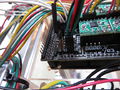
The black wire is connected to the positive Z_min pin through a diode.
See steps to reproduce below.


12 V directly from power supply. I did a quick and dirty solder directly to 12 V connectors, just to test if it works. The important steps are:
- Lower print head so it just touches print bed.
- Let sensor rest its blue end on bed with the nuts on its body just touching the mount point (side of fan in pic above).
- Put something of thickness ~0.5mm between blue sense head and print bed.
- Fixate sensor. In the pic above, this is done with two zip ties running around the fan.

Firmware
Updated Marlin in repo to auto bed compensate. You might want to fiddle with lines 400 - 402 of Configuration.h. They contain X, Y and Z_PROBE_OFFSET_FROM_EXTRUDER, These values define the sensor's position relative to the print head. X and Y are not important to get extremely accurate. Z_PROBE_OFFSET_FROM_EXTRUDER must be within 0.1 mm to get reasonable first layer heights.
I used trial-and-error to setup Z_PROBE_OFFSET_FROM_EXTRUDER. Thomas Sanladerer presents a more rigorous procedure here: https://www.youtube.com/watch?v=EcGFLwj0pnA
Usage
The printer will do the probing procedure upon receiving the G29 command. Bed compensation will be performed on every normal G1 or G0 move after that.
Posted video of homing followed by a nine-point probing procedure:
.
Here's another video showing probing directly on the MK2A heat bed:
Summary
Links to Replications
- Automatic Bed Leveling - Marcin 3/6/16