PVC Pipe and Fittings Library: Difference between revisions
| Line 121: | Line 121: | ||
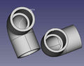
File:elbow.png |'''1" PVC Elbow''' - size:19kb - FreeCAD -[[File:1"-pvc-elbow.fcstd]], | File:elbow.png |'''1" PVC Elbow''' - size:19kb - FreeCAD -[[File:1"-pvc-elbow.fcstd]], | ||
File:elbowcomp. | File:elbowcomp.jpg |Note slight difference compared to generated - 0.15" wall for generated, 0.12 for downloaded. | ||
File:1"-pvc-tee.png |'''1" PVC Tee'' - size:4kb - FreeCAD -[[File:1"-pvc-tee.fcstd]], | File:1"-pvc-tee.png |'''1" PVC Tee'' - size:4kb - FreeCAD -[[File:1"-pvc-tee.fcstd]], | ||
| Line 129: | Line 129: | ||
</gallery> | </gallery> | ||
=Macros= | =Macros= | ||
Revision as of 02:18, 24 January 2018
Pipes
The dimensions of the PVC pipes can be found here PVC_Pipe. Wikipedia on Nominal Pipe Size (NPS) [1],
We will use following guide line for position of a pipe: put one end (base) of the pipe onto the x-y plane. The center of the base has coordinate (0,0,0). The other end points to the positive direction of the z-axis.
Rationale: This is the same way FreeCAD places a new cylinder. We mimic the FreeCAD behavior for UI consistancy.
The default pipe length is 1ft. This is an arbitrary choice. When I use a macro, it will store the last length used by the user.
Macro
To create Pipes 40 and 80 Schedule PVC pipes use File:Create-pipe.fcmacro.


Elbows
Useful links: [2]
90° - Elbows
Described by 3 dimensions: pipe size, schedule, G,H,M. Other dimensions are derived from NPS pipe-dimensions.
One can create 90° with alpha°-elbow macro. Just set alpha=90° and J = H. I do not know why my parameter list uses "H" for 90°-elbows and "J" for other elbows.
Macro
To create an 90° elbow, run File:Create-elbow-90.FCMacro.


alpha° - Elbows
alpha, pipe size, schedule, H,J,M. Other dimensions are derived from NPS pipe-dimensions.
Macro
To create an elbow with an arbitrary alpha from 0° to 180°, run File:Create-elbow-alpha.FCMacro.


Couplings
General (Centric)
A general coupling is used to create reducer and simple couplings.
The general coupling is described by 9 dimensions: POD, PID, POD1, PID1, X1, X2, N, M, M1. The dimensions POD, PID, POD1, and PID1 are derived from the pipe sizes. The are abbreviations of Pipe Outer Diameter and Pipe Inner Diameter. The dimensions X1 and X2 are not official dimension names.

The offset a1 is calculated in such a way, that the thinest part of the middle section is not smaller that walls on of the sockets on both sides. Lengths a2, a3, a4 and angle b1 are derived from the dimensions and are only used to calculate a1.
Simple Coupling
A general coupling is described by 10 Dimensions: POD1, PID1, L, M, N. The dimensions POD1 and PID1 are not from a official specifications. They are derived from pipe size and schedule.

Macro
Run File:Create-coupling.fcmacro to create a simple coupling.
Reducer
The reducer coupling is described by 8 Dimensions: 4 Pipe dimensions (they follows from pipe sizes and schedule), L, M, M1, and N.

Macro
Run File:Create-coupling.fcmacro to create a reducer coupling.


Notations
- O.D. - outer diameter.
- Average I.D. - average inner diameter (why average?). This dimension determines the size of the pipe.
- Min. Wall - thickness of the pipe wall.
- Schedule - determines (indirectly) the thickness of the wall.
Notes
"O.D." = "Average I.D."+2"Min. Wall"
Tees
Almost General Tees
Described by parameters G, G1, G2, H, H1, H2, M, M1, and pipe dimensions. As pipe dimensions we use POD, POD1, PID, PID1.

Macro
Run File:Create-tee.fcmacro to create a tee.


Simple Tees
Described by parameters G, G1, H, H1, L, M, and pipe dimensions. As pipe dimensions we use POD, POD.

Macro
Run File:Create-tee.fcmacro to create a tee.
Genaerated Library Parts
SCH80 1" PVC pipe - size:4kb - FreeCAD -File:Pvc-pipe-test.fcstd,
90°-elbow test file - size:17kb - FreeCAD -File:Pvc-elbow-90-test.fcstd,
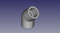
alpha°-elbow test file. Here alpha° is 45°. - size:19kb - FreeCAD -
,

Tee test file - size:24kb - FreeCAD -File:Pvc-tee-test.fcstd

Coupling test file - size:12kb - FreeCAD -File:Pvc-coupling-test.fcstd
Library of STEP Downloads from McMaster Carr
Not recommended due to significantly larger file size than the generated versions
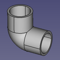
1" PVC Elbow - size:19kb - FreeCAD -File:1"-pvc-elbow.fcstd,
Note slight difference compared to generated - 0.15" wall for generated, 0.12 for downloaded.
- 1"-pvc-tee.png
'1" PVC Tee - size:4kb - FreeCAD -File:1"-pvc-tee.fcstd,
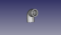
- 1"-pvc-valve.png
'1" PVC Valve - size:4kb - FreeCAD -File:1"-pvc-tee.fcstd,


Macros
Macros are now in a git repository for the macros is [3]. The CSV tables with parameters can be found in [4]
The elbow macro depends now on other files. See README.md for installation instructions.
Installation
- Download ose-piping-library. To run the macros you only need the content of the directory macros. It contans macro files with extension .FCMacro, drawing with dimensions .png and some .csv tables with part parameters for testing. The more realistic .CSV tables can be downloaded from [5].
- Determine the directory where FreeCAD looks for macros: Menu "Edit"->"Preferences"->"Macro". Look at the settings "Macro path". It is for example "/home/ose-developer/.FreeCAD/Macro/".
- Now copy all files from the downloaded macros directory to the FreeCAD macro directory. In this example "/home/ose-developer/.FreeCAD/Macro/".
- Select a FreeCAD menu item "Macro"->"Macros..." then select the corresponding macro -- it startart with "create-..." and click "Create".

How to create a pipe macro
Steps to create GUI: The original instruction are taken from [6] but I (Ruslan) have problems with them. I adjusted them to FreeCAD.
- Create with QT Designer a Dialog based on QDialog class. Save the name for example add-nps-pvc-pipe-dialog.ui.
- Convert add-nps-pvc-pipe-dialog.ui to python code running
- pyside-uic add-nps-pvc-pipe-dialog.ui -o pipe-dialog.py
- or call
- pyside-uic --indent=0 add-nps-pvc-pipe-dialog.ui -o pipe-dialog.py
- to use tabs as indention.
- If you use the FreeCAD macro editor, pay attention that the indention of pyside-uic and of the editor are the same.
- Insert content of the methods setupUi(self, Dialog) and retranslateUi(self, Dialog) from pipe-dialog.py (How can I insert here a block of python code?) into your macro file.
FAQ
- Do we really want to 3D-print pipe fittings? Somehow I have doubt about mechanical properties of the 3D-printed products.
- Yes. For high pressure applications - 300 PSI - we would have to be very careful. For low pressure, such as 5 PSI, it's not a problem. Eventually, we want to refine printing techniques where our fittings can do what standard schedule 80 ABS fittings can do.