Hydraulic Valve: Difference between revisions
| Line 56: | Line 56: | ||
<html><img src="http://www.modernhydraulics.net/images/hydes/uploads/2011/01/sequence-valve.jpg"></html><br/> | <html><img src="http://www.modernhydraulics.net/images/hydes/uploads/2011/01/sequence-valve.jpg"></html><br/> | ||
Image Source: [http://www.modernhydraulics.net/tag/sequence-valves Modern Hydraulics] | Image Source: [http://www.modernhydraulics.net/tag/sequence-valves Modern Hydraulics] | ||
When Fluid cannot travel from the inlet to the outlet, the pressure buildup inside the valve opens the valve and the fluid travels to the other actuator. | |||
==Sequence Valve Circuit, Cylinder and Motor== | |||
Example: Soil Mixer 2019. We want to spin a motor nonstop but also move a cylinder quickly when we want to using an open center system. One way to achieve this is with a sequence valve. The cylinder is the primary actuator. We put the sequence valve before the cylinder valve and use an all ports blocked in neutral type spool so that when the cylinder is not being used the sequence valve opens and the flow is directed to the hydraulic motor. | |||
=Industrial Manifold Standard= | =Industrial Manifold Standard= | ||
Revision as of 17:54, 17 December 2019
Hydraulic valves modify the flow of hydraulic fluid through a circuit. See Also: Hydraulic Valves
Directional Control Valves
Abbreviated DCV, these are commonly used to control flow to hydraulic actuators, motors and cylinders. They consist of a valve body, a spool, a lever or solenoid, and a spring.
A DCV is categorized by # of Ways and # of Positions. Ways refer to the ports for fluid to enter or exit the valve. Positions refer to the positions of the spool.
The spool is the moving part within the valve that blocks or opens ports. They are commonly cylindrical, hence the name Spool.

Example: a 4 way, 3 position DCV has 4 ports (typically Pressure, Tank, output A, and output B) and 3 spool positions.
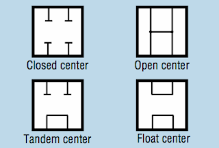
Spool Types
A common arrangement would be:
- P->A, B->T
- P->T, A blocked, B blocked
- P->B, A->T
This is shown in the following image as the Tandem configuration.
DCV Links
- Hydraulics & Pneumatics DCV eBook Chapter Bud Trinkel
- Forum discussion Open Center Spools vs Tandem Spools
- Forum discussion on valve spool types
Check Valves

A check valve allows flow in only one direction. Typically these are a simple device consisting of a ball, a spring and a cone shaped orifice that seals with the ball. The spring forces the ball to seat against the cone and any additional pressure further seals the valve. Only flow with enough force to overcome the spring force can flow through the valve, and only in one direction.
Pilot Operated Check Valves
A pilot-operated check valve only allows reverse flow when there is sufficient pressure on the pilot port. Also called Pilot-op check valves. Fluid flows freely in one direction. In the reverse direction pilot pressure must be applied to the pilot port.

Source:Bud Trinkel
On the left is an example circuit that uses pilot operated check valves that prevents a cylinder from moving when the spool is in the center position. This circuit overcomes the failure of a typical metal valve spool to seal with the valve body.
These are sold by surplus center. Example: Item number: 9-8408-50. This has a Pilot Ratio of 4:1.
Pilot Ratio
Pilot Ratio is the ratio of Pilot Piston Area to Valve Seat Area where the pilot piston is the area of the actuator in the valve, and the valve seat area is the area of the valve where the ball seals. An important consideration when choosing a Pilot-Operated Check Valve is the Pilot Ratio in relation to the cylinder's Cylinder Internal Ratio: Piston Area to Rod-end Annular Area. For a 5x8x2.5 cylinder, as used in earlier CEB presses, the Cylinder Internal Ratio is 2. According to Bosch-Rexroth (see links), you must have a pilot ratio much larger than a cylinder internal ratio when controlling flow from the annular chamber (rod end chamber). Thus, the surplus center valve above is suitable for the CEB press cylinder as its ratio is twice as large as the cylinder's internal ratio.
Limits of Pilot-Operated Check Valve Circuits
The limit becomes the load-induced pressure that the pilot pressure must overcome. In the case of the CEB press, the load-induced pressure on the piston side is that of the piston, rod, press platen, and a CEB. Lets exaggerate that to 250lbs.
250lbs / (2.5"^2 *3.14) = 12.8psi
This is easily overcome, so using a pilot-operated valve on the CEB press is possible. If we were dealing with a much larger load and a lower system pressure, the pilot-operated check valve would not work to hold our cylinder stationary.
Links
Sequence Valves

Image Source: Modern Hydraulics
When Fluid cannot travel from the inlet to the outlet, the pressure buildup inside the valve opens the valve and the fluid travels to the other actuator.
Sequence Valve Circuit, Cylinder and Motor
Example: Soil Mixer 2019. We want to spin a motor nonstop but also move a cylinder quickly when we want to using an open center system. One way to achieve this is with a sequence valve. The cylinder is the primary actuator. We put the sequence valve before the cylinder valve and use an all ports blocked in neutral type spool so that when the cylinder is not being used the sequence valve opens and the flow is directed to the hydraulic motor.
Industrial Manifold Standard
https://docs.google.com/open?id=0BwxMMqGvwTM-eHpYRGdOVTZ2VU0
D03
casting
lost wax idea
https://docs.google.com/open?id=0BwxMMqGvwTM-MlM0Z09uMzQ0RlE
two molds. inner and outer. sand and plaster? make outer mold. fill and cure 3d printed inner mold. insert into outer mold. pour alum(?) in and melt abs. mill bottom flat. mill hole through spool area. tap ends to attach solenoids.