Hydraulic Valve
Hydraulic valves modify the flow of hydraulic fluid through a circuit. See Also: Hydraulic Valves
Overview
good overview of valves and their configurations in applied circuits
Directional Control Valves
Abbreviated DCV, these are commonly used to control flow to hydraulic actuators, motors and cylinders. They consist of a valve body, a spool, a lever or solenoid, and a spring.
A DCV is categorized by # of Ways and # of Positions. Ways refer to the ports for fluid to enter or exit the valve. Positions refer to the positions of the spool.
The spool is the moving part within the valve that blocks or opens ports. They are commonly cylindrical, hence the name Spool.

Example: a 4 way, 3 position DCV has 4 ports (typically Pressure, Tank, output A, and output B) and 3 spool positions.
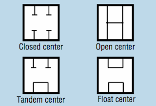
Spool Types
A common arrangement would be:
- P->A, B->T
- P->T, A blocked, B blocked
- P->B, A->T
This is shown in the following image as the Tandem configuration.
Pressure on DCV Tank Port
One important consideration is how much back pressure can be seen on the T port of the DCV. Often, this will be 0psi - the tank port should only be sent to tank.
There are other valves that can see high pressure on the tank port. See page 8 of this Eaton Catalog for an example of a tank port pressure rated valve.
Another example is this Yuken Spool catalog page:

DCV Pressure Drop
Energy lost to a DCV due to its operation can be found on a manfucaturer's Pressure Drop vs Flow Rate graph. Here is one such graph from Eaton.

You will see different curves shows on the graph. These are for different spool types and flow paths. I have truncated the list of spool types for a typical tandem center spool valve. This valve shows that we look at curve 9 for P->A and P->B flow. So for example, lets say we have a flow of 10GPM. Look at curve 9 at 10GPM and we see a value of about 110PSI. Now, from A/B->T we look at curve 5 and see that at 10GPM we have about 70PSI. Total drop across valve when pushing 10GPM in and 10GPM out (real life will not see same input and output flow due to cylinder geometry) will be 180PSI. When the valve is not in use, we will see a pressure from from P->T of 65PSI.
All valve types (not only DCVs) will show a Pressure Drop vs Flow Rate graph in their datasheet.
DCV Links
- Hydraulics & Pneumatics DCV eBook Chapter Bud Trinkel
- Forum discussion Open Center Spools vs Tandem Spools
- [https://www.tractorbynet.com/forums/hydraulics/137518-tandem-center-vs-open-center.html Forum discussion on valve spool types
Check Valves

A check valve allows flow in only one direction. Typically these are a simple device consisting of a ball, a spring and a cone shaped orifice that seals with the ball. The spring forces the ball to seat against the cone and any additional pressure further seals the valve. Only flow with enough force to overcome the spring force can flow through the valve, and only in one direction.
Pilot Operated Check Valves
A pilot-operated check valve only allows reverse flow when there is sufficient pressure on the pilot port. Also called Pilot-op check valves. Fluid flows freely in one direction. In the reverse direction pilot pressure must be applied to the pilot port.

Source:Bud Trinkel
On the left is an example circuit that uses pilot operated check valves that prevents a cylinder from moving when the spool is in the center position. This circuit overcomes the failure of a typical metal valve spool to seal with the valve body.
These are sold by surplus center. Example: Item number: 9-8408-50. This has a Pilot Ratio of 4:1.
Pilot Ratio
Pilot Ratio is the ratio of Pilot Piston Area to Valve Seat Area where the pilot piston is the area of the actuator in the valve, and the valve seat area is the area of the valve where the ball seals. An important consideration when choosing a Pilot-Operated Check Valve is the Pilot Ratio in relation to the cylinder's Cylinder Internal Ratio: Piston Area to Rod-end Annular Area. For a 5x8x2.5 cylinder, as used in earlier CEB presses, the Cylinder Internal Ratio is 2. According to Bosch-Rexroth (see links), you must have a pilot ratio much larger than a cylinder internal ratio when controlling flow from the annular chamber (rod end chamber). Thus, the surplus center valve above is suitable for the CEB press cylinder as its ratio is twice as large as the cylinder's internal ratio.
Limits of Pilot-Operated Check Valve Circuits
The limit becomes the load-induced pressure that the pilot pressure must overcome. In the case of the CEB press, the load-induced pressure on the piston side is that of the piston, rod, press platen, and a CEB. Lets exaggerate that to 250lbs.
250lbs / (2.5"^2 *3.14) = 12.8psi
This is easily overcome, so using a pilot-operated valve on the CEB press is possible. If we were dealing with a much larger load and a lower system pressure, the pilot-operated check valve would not work to hold our cylinder stationary.
Links
Sequence Valves

Image Source: Modern Hydraulics
When Fluid cannot travel from the inlet to the outlet, the pressure buildup inside the valve opens the valve and the fluid travels to the other actuator.
Sequence Valve Circuit, Cylinder and Motor
Industry Example: Motor and Cylinder Circuit
This is from a Weed Badger agricultural implement. They want to spin a cultivator motor but want to be able to also run a swing cylinder to move the cultivator in between trees in an orchard or vineyard setting. The cylinders need to get priority to shift immediately. The sequence valve is used in conjunction with "closed center valves" (all ports blocked in neutral) switching cylinders in an open center hydraulic system.
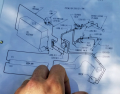
Weed Badger Hydraulic Diagram
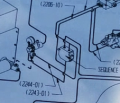
Closeup of Sequence Valve
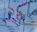
I added arrows to indicate flow. Red is fluid from pump, blue is return lines, orange is sequence valve controlled flow.


OSE Case
Example: Soil Mixer 2019. We want to spin a motor nonstop but also move a cylinder quickly when we want to using an open center system. One way to achieve this is with a sequence valve.
- The cylinder is the primary actuator.
- We put the sequence valve in parallel with the cylinder valve
- Use an all ports blocked in neutral type spool
- When the cylinder is not being used the flow is blocked and pressure builds on the branch from the pump to the parallel valves.
- Due to this pressure, the sequence valve opens and the flow is directed to the hydraulic motor.
- The flow remains to the motor until the cylinder valve opens, reducing pressure in the sequence valve.
I'm not sure but I think the amount of flow to the motor will be proportional to the PSI on the line to the cylinder valve - it's not all or nothing. This is useful for our application. We can flow control the cylinder and still have flow going to the motor. The sequence valves are sold in high, medium, and low switch-point models. 40-350psi low, 350-1700psi medium, and 1400-2500psi high. Using a medium set-point sequence valve, we could divide flow between the motor and the cylinder for the duration of the cylinder's actuation. Once again, not sure.
Limitations
The limitation of the above design is that you lose a lot of power through the valve. If you have any load on the cylinder then you must choose a sequence valve that has a setpoint proportional to your load. Therefore you will not switch flow to the second circuit until pressure reaches maximum cylinder working pressure. For example, if your cylinder sees 1000psi at its inlet during normal working conditions, you choose a sequence pressure of ~1050 PSI. No fluid goes to secondary circuit under 1050 psi. So for a 15GPM system, you lose:
1050PSI * 15GPM / 1714 = 9.2 HP!
Aidan Williamson (talk) 18:09, 16 July 2021 (UTC)
Flow Divider Valve
Read Article: Hydraulics Pneumatics Available with equal or split ratio cartridges, these valves divide flow. Can cascade. Variations between branches likely.
Priority-type set a flow for one output branch and put excess flow to other output.
Proportional divider valves are mechanically or electronically governed valves that divide flow rate to two branches.
Fixed Flow Priority Divider Valve
For this section I'll focus on the Prince Hydraulics RD-400 valve. This is available from Surplus Center for about $130. This valve will split an inlet flow into two pressure compensated outlet flows at a fixed priority flow to inlet flow ratio between 1.5:30 to 14:30. Because the valve is pressure compensated, changes in inlet and outlet pressures will not affect the flow to the priority port. The Three ports would be Inlet, Controlled Flow (CF) or Priority, and Excess Flow (EF) ports.

In the schematic above we can see that this is simply two pressure compensated flow controls. The vertical arrow means pressure compensation.
The limitation of this valve is that the CF is fixed and cannot be shut off. If you are using a DCV upstream of the CF port, it had better be an open center type (tandem, float, open center) or a pressure relief valve installed (factory with RD-400R types).
Pressure Drop Across Valve
Here is an example of a fixed flow priority divider valve sold by Hydraforce as a "Flow Regulator" model FR16-30F capable of 50GPM input. Pressure Drop vs Inlet Flow from Hydraforce Website:

OSE Use Case
Here is an example of a CEB Press circuit utilizing a Fixed Flow Priority Divider Valve.

Priority On Demand (Steering Priority Valve)
Also known as a load sensing priority valve.
A priority on demand valve is an interesting mix between a flow divider and a sequence valve. It differs from a sequence valve in that the oil can flow to the excess flow circuit at as little as 80PSI. You don't need to set the valve to switch at the maximum pressure requirement for the actuator it gives priority to. The priority on demand valve can enable sub-circuit load sense capability using fixed displacement hydraulic pumps. These valves emerged from the need to have full flow to a power steering circuit that is fed from a tractor's or other mobile hydraulic equipment's open center system. The steering system must be given full hydraulic power even when another (potentially less flow restrictive) circuit is opened. Hence the name Priority On Demand Valve.

Please take a look at the above schematic taken from a Bucher Hydraulics catalog. Let's make some observations about the valve.
|-*3 port
- 2 Position
- Infinitely Variable (extra lines on outside of valve body)
- Pilot Pressure Actuated
- Spring Returned
- Port Identification:
- 1: Load Sense (LS) signal port
- 2: Excess Flow Port (EF)
- 3: Inlet Flow
- 4: Controlled Flow Outlet (CF)
Observe also the variable orifice pictured as part of the schematic but not part of the valve body. This is commonly a closed center directional control valve (usually an oribtrol valve) that would switch flow to the priority hydraulic actuator.
The spring that returns the valve to the normal position usually has an equivalent PSI rating of between 80 to 400psi. The pilot line that shifts the valve to allow flow to the EF port is connected to the priority outlet of the valve. Therefore, when pressure rises at the CF output, the valve will shift flow to the EF port. In addition to the spring return, there is another pilot line that can be referred to as a "Load Sense" (LS) line. This load sense line also taps in to the outlet of the priority flow divider valve but it does so after the DCV orifice. This LS pilot pressure counteracts the pilot pressure on the other side of the valve and maintains flow to CF port. Therefore, we have our spring force plus our load sense force keeping the flow to the priority device even though pressure is raising the in priority circuit. The load sense line should have a pressure relief valve which limits maximum priority circuit pressure and allow the line to drain to tank. So when the CF line is pressurized, the valve will shift flow to EF UNLESS Load Sense pressure is present, in which case the valve will shift only when CF port pressure > Spring Pressure + LS Pressure.
OSE Use Case
To imagine this valve in use, let's think about the Soil Mixer 2019. Here is a schematic that I drew to explain the function of this type of valve.
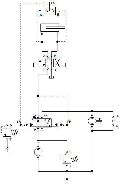
Unlabeled Diagram
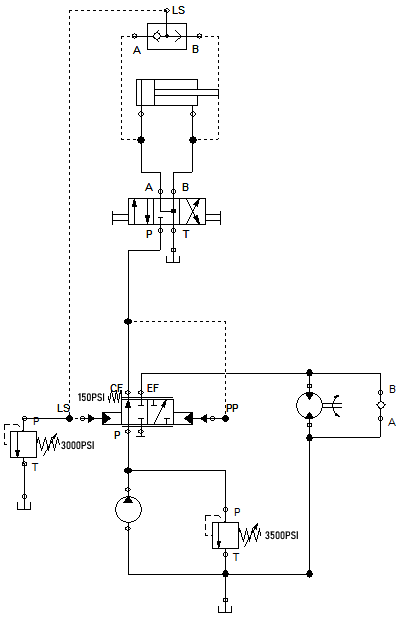
PSI ratings of components labeled
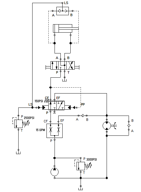
Added flow control to reduce cylinder GPM


Let's work through this in chronological order. We power on the hydraulic pump which can supply 30GPM at 3500PSI. The oil is pumped into the valve valve and out to the CF port. Because this is a closed center valve, pressure builds at the CF port and the pilot line to the PP port. The PP port must overcome the spring pressure (which for this example let's say is 150PSI) in order to shift the valve. The pump easily supplies 150 PSI and the valve begins to shift. Now oil at 150 psi goes to our motor which gives maybe about 1500psi of resistance without a soil load. Now we have a pump outlet pressure of around 1700PSI and the motor is spinning. We decide to add some soil so we shift the DCV to extend the cylinder. Now our pressure on the CF and PP ports drop so the valve shifts to push flow to the CF port. Our load of soil causes the cylinder to see 500PSI of pressure at the output of the DCV and this 500PSI is ported through a shuttle valve to the LS port of the priority flow valve. Now we have 500PSI oil pressure + 150PSI spring pressure on the left side of the valve and only ~500psi on the right side of the valve. The valve maintains flow to the CF port. Our cylinder reaches max stroke and the pressure at the cylinder's inlet port shoots up to maximum PSI. The LS line pressure relief valve is set to 500PSI less than maximum system pressure. This means that when the cylinder bottoms out, we see more pressure on the right side of the priority valve than on the left side (PP > LS+Spring). Therefore, the valve will shift to allow flow to the EF port once again. The DCV doesn't even have to shift for this shift in oil flow to take place. However, once the DCV does shift, we now will have 0 PSI at our load sense port because of the float center valve and our oil flows to the motor at only the 150PSI spring pressure.
Now, the above scenario is not perfect. For instance, we don't want 30GPM going to the small soil drawer cylinder. Instead, we want maybe 15gpm. One solution is to put a pressure compensated adjustable flow control valve such as the Prince RD-1900 upstream of the prioiry flow control valve. This could split flow from the pump to the motor and priority valve. Flow from the EF port of the prioirty valve could then be recombined with the output of the original flow control and be sent to the motor. Another option would be a needle valve before the cylinder DCV. In this case, the PP would read the pressure on the upstream side of the needle valve and would shift the valve to provide flow to the motor instead of the cylinder.
Compare this to the sequence valve example from above. In the sequence valve circuit, flow is diverted to the motor at 1050PSI, losing about 9 horsepower before reaching the motor. In the Priority On Demand circuit, fluid is diverted at 150PSI, losing only 1.3HP.
These valves are available off-shelf and can also be found used on tractors and other mobile hydraulic equipment. The most economical way to implement a priority flow control valve would be to use a cartridge valve. These must be combined with a 4 way valve block with proper cavity. The total cost of the two components - valve and block - most likely will not exceed $150.
Further Information Regarding Priority On Demand Valves
- Eaton Catalog - see page 9 and on
- Eaton PRFS-16 Eaton cartridge valve example
- Bucher Catalog
- Hystat Channel Video - helpful video on youtube about these valves from user Hystat
- Hydraforce EC16-42 Priority on Demand Cartridge Valve
Cartridge Valves
Cartridge valves are cylindrical valves that you screw into a location on an industry standard valve body called a "cavity". Cartridge valves are inexpensive standardized valves that can perform virtually any valve function and save space in hydraulic systems. They can be standalone on a single valve body or can screw into a manifold.
Logic Valves
When properly implemented, poppet type logic cartridge valves can be like the relays of hydraulics - allowing small pilot flows to control large flows up to 50GPM with size 16 cartridges.
The simplest cartridge valve is a logic valve which has three ports: X, A, and B.
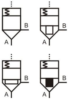
In the above picture found on the web, the X port is on top and is not labeled. Analyzing these pictures from left to right, top to bottom, we see the first example will allow flow from A to B when X is vented to tank and pressure at A exceeds spring pressure. This is a balanced logic valve because area of A and area of X are equal. In the next picture we have an unbalanced valve. This means that X area is greater than A area. In this valve, fluid can flow from B to A when X is vented and pressure at B exceeds the spring value at X as well as A to B under same conditions as the first valve. The third picture is the same as the second but with a smaller annular area at port B. The ratio of Area of A port to Area of X port is referred to as the Area Ratio. In the second picture, the ratio is >0.7 and in the third picture it is <0.7. The fourth picture is a logic valve with a damping nose. This just means it cushions as it opens and closes.
Directional Control of a Cylinder with Logic Valves
The benefit of this is that a low flow DCV can control pilot pressures to high-flow-rated, inexpensive logic valves.
image source: valvehydraulic.info

Other Cartridge Valves
Cartridge valves can do more than just open at specified pressures. Pretty much any standalone valve can come in cartridge form. For example, here is a priority on demand flow control cartridge valve from Hydraforce:

Notice that there are 4 ports on this cartridge. This must be matched with an appropriate valve body or manifold cavity.
Industrial Valve Body Standards
Valve bodies are specified with two size criteria: Size and # of Ways. For example a Size 4 2way valve body has two SAE 4 ports in addition to a size 4 cavity.
The larger the cavity size, the more ways you can have. A size 4 can only have up to 3 ways while a size 16 can have up to 4 ways.
Not all the ports should always be the same size. For example, load sensing port may be a -4 size while an outlet port may be a -12 size. This Hydraforce valve body is a good example of that.

Depending on manufacturer, you may also be able to specify material of valve body. Aluminum, steel, and ductile iron are common options.
Links
- Parker Industrial - standard valve bodies and cavities
Industrial Manifold Standard
https://docs.google.com/open?id=0BwxMMqGvwTM-eHpYRGdOVTZ2VU0
D03
casting
lost wax idea
https://docs.google.com/open?id=0BwxMMqGvwTM-MlM0Z09uMzQ0RlE
two molds. inner and outer. sand and plaster? make outer mold. fill and cure 3d printed inner mold. insert into outer mold. pour alum(?) in and melt abs. mill bottom flat. mill hole through spool area. tap ends to attach solenoids.