Power Cube/Manufacturing Instructions/Fabrication June 2011: Difference between revisions
(→BOM) |
|||
| Line 130: | Line 130: | ||
| Plate||3.5"||1/4"||100" | | Plate||3.5"||1/4"||100" | ||
|- | |- | ||
| Tube||6" | | Tube||6"||1/4"||14" | ||
|} | |} | ||
Revision as of 02:43, 13 June 2011
![]() This page is currently under construction and might undergo drastic changes within a short span of time.
This page is currently under construction and might undergo drastic changes within a short span of time.
=Power Cube 4.0 Construction
Here's how to replicate our Powercube 4.0 design. Keep in mind that this the powercube is still at the prototype stages and designs are likely to change.
Jig (optional)
The jig is an optional piece of fabrication equipment that can be very useful to have if you are creating a bunch of these.
Materials List
Steel
14' Angle 2" (1/4")
7'2" Rebar (1/2")
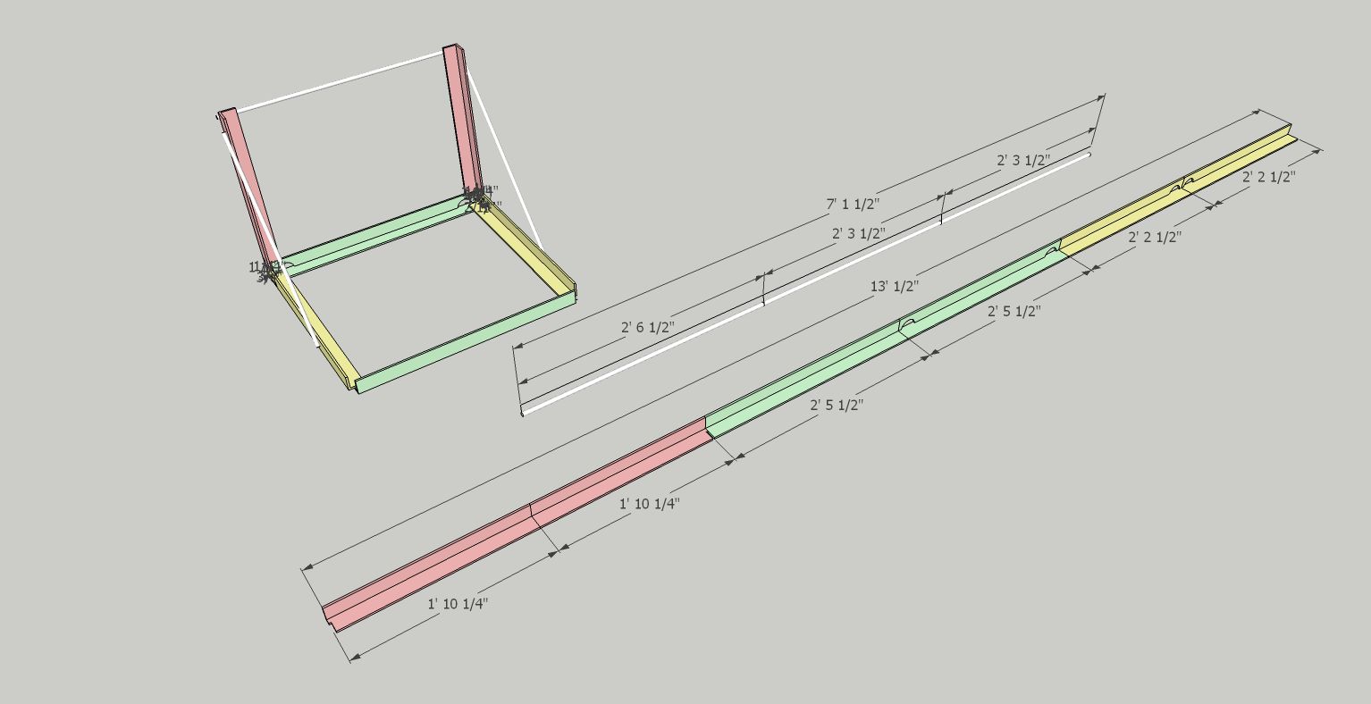
Cut List
Angle
 1'10 1/4"   x2  (red)
 2'5 1/2"    x2  (green)
 2'2 1/2"    x2  (yellow)
Rebar
 2'6 1/2"
 2'3 1/2"    x2
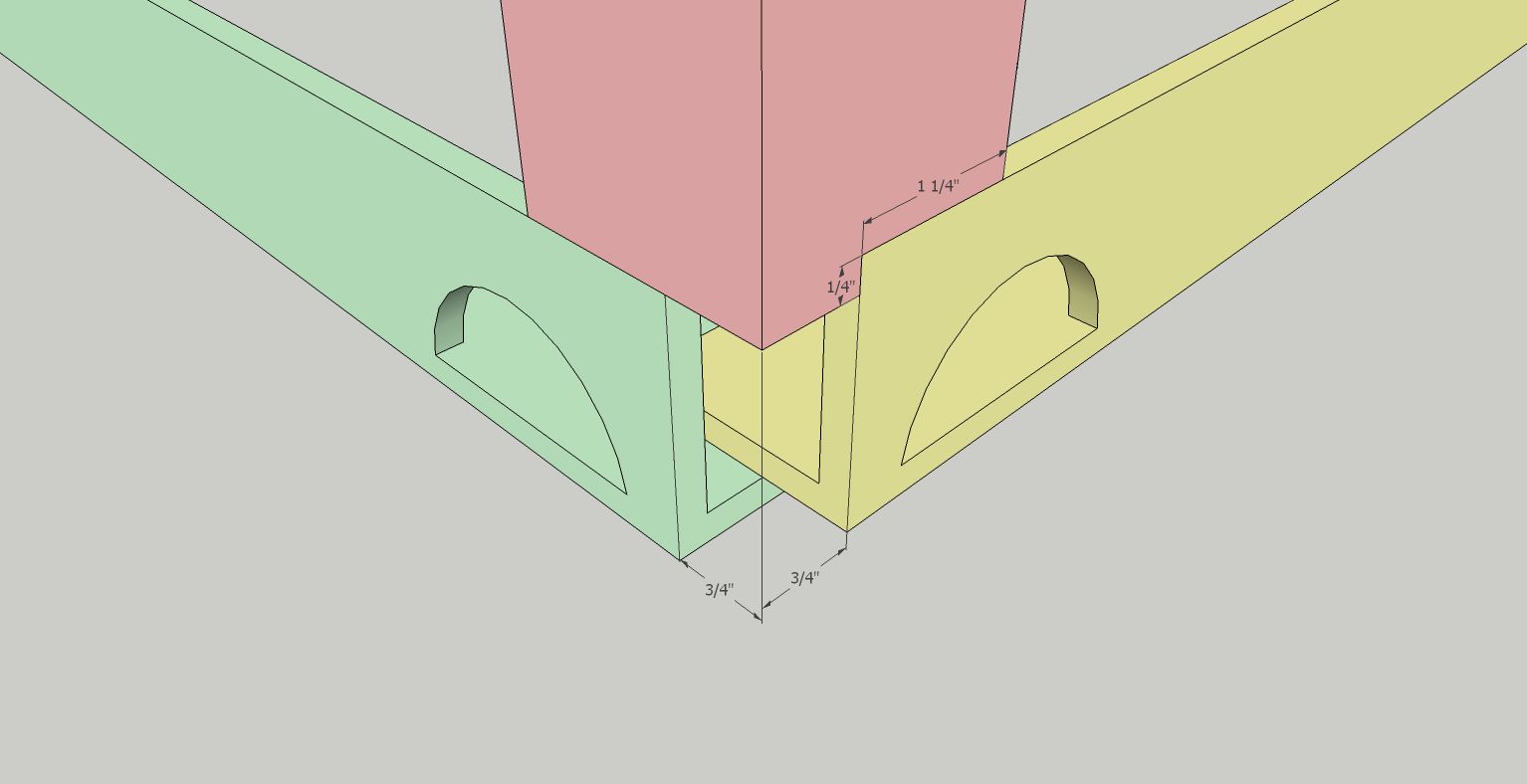
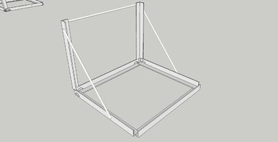
Assembly of the Jig is fairly straight forward. Tack and weld the pieces in place. Be sure to note the overlapping order and the notch made at the bottom of the 1'10 1/4" piece (red).
 Also note that the corners are offset 3/4" to give room for the cube to sit snugly in the frame (and a convenient gap for welding the corners.)
1'10 1/4" (red) 2'5 1/2" (green) 2'2 1/2" (yellow)
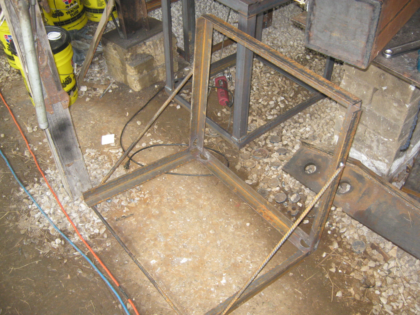
Torch holes in the corners below the frame as seen above. This allows room for the welding torch to get to the PowerCube while welding.
Jig fully assembled.
Frame
Power Cube
BOM
| Name | Quantity | Dimensions | Type |
| ENGINE ASSEMBLY | 1 | ||
| Engine | 1 | ||
| Mounting Plate - Hydraulic Motor | 1 | 8"x10"x1/4" | Flat |
| Connector Plate | 1 | 8"x3.75"x1/4" | Flat |
| Mounting Angle | 2 | 8"x(2"x1/4") | Angle |
| Engine Mount Plate | 1 | 8"x23"x1/4" | Flat |
| Lovejoy Coupler | 1 | 2.5"x2.25" | Cylinder |
| Hydraulic Motor | 1 | ||
| Gas Tank | 1 | 14"x6"x6" | Box |
| FUEL FILTER ASSEMBLY | 1 | ||
| Fuel Filter Fitting | 1 | ||
| Fuel Filter | 1 | 3.5"x5" | Cylinder |
| FRAME ASSEMBLY | 1 | 24"x27.5"x30" | Box |
| 24" Angle | 4 | 24"x(2"x1/4") | Angle |
| 27" Angle | 4 | 27"x(2"x1/4") | Angle |
| 29" Angle | 6 | 29"x(2"x1/4") | Angle |
| HYDRAULIC TANK ASSEMBLY | 1 | 19"x29"x4" | Box |
| Hydraulic Tank Plates | 2 | 19"x29"x1/4" | Flat |
| Flat - Hydraulic Sides | 2 | 19"x3.5"x1/4" | Flat |
| Flat - Hydraulic Bottom/Top | 2 | 3.5"x28.5"x1/4" | Flat |
| Battery | 1 | 5"x6"x7.5" | Box |
| Hydraulic Mount | 2 | 4.75"x3" | Cylinder |
Metal purchase
(easier to read).
| Type | Width | Thickness | Total Length (rounded up) |
| Angle | 2" | 1/4" | 400" |
| Plate | 19" | 1/4" | 60" |
| Plate | 8" | 1/4" | 40" |
| Plate | 6" | 1/4" | 12" |
| Plate | 3.5" | 1/4" | 100" |
| Tube | 6" | 1/4" | 14" |
Frame Welding Jig
- List frame welding jig materials cut list:
- Show Sketchup picture of cut list:
- Show Sketchup of finished jig:
- Show picture of ...
- etc
- etc
- etc
Hydraulic Reservoir
Fuel Tank
CNC Torch Required Materials
(if CNC Torch Table not available, torch manually)
Motor Plates
Torch Required Materials
Assemble and Weld
- Prepare 12 frame members:


