LifeTrac III/Manufacturing Instructions: Difference between revisions
Jump to navigation
Jump to search
Tom Griffing (talk | contribs) No edit summary |
Tom Griffing (talk | contribs) |
||
| Line 105: | Line 105: | ||
====¼” x 4" x 4" Steel Tube==== | ====¼” x 4" x 4" Steel Tube==== | ||
* Verify the following 4" x 4" tubes have already been cut: | |||
::[[Image:Cut4x4Tubes.png]] | |||
* 3 Lower cross members | * 3 Lower cross members | ||
** Drill holes at 14", 46" | ** Drill holes at 14", 46" | ||
Revision as of 05:40, 30 October 2011
| LifeTrac III | ||
|---|---|---|
| Home | Research & Development | Bill of Materials | Manufacturing Instructions | User's Manual | User Reviews | 
| |
| ||||||||||||||||||||||||||
Overview
LifeTrac is a low-cost, multipurpose open source tractor. It serves as a workhorse backbone for many of GVCS technologies.
Featuring a modular design and detachable PowerCube units, it has the ability to rapidly switch between a variety of GVCS machines via the QA Plate. The machine is overbuilt with a focus on lifetime design and ease of repair.
Four hydraulic motors provide skid steer power to the wheels, and a unique chain tread system enables navigation of fairly extreme terrain.
Preparation
Safety
- Hearing Protection
- Eye Protection
- Steel Toe Boots
- Welding
- Gloves
- Hood
- Apron/Jacket
Workspace
This section describes the various workspace areas that we have found to be useful in fabricating the LifeTrac. It is provided as a suggestion for preparing your work area.
- Storage: For raw steel and parts
- Cutting Area: For use with cutting torch - Made from non-flammable materials
- Welding Table: Usually steel, suitable for use with arc welder (MIG, TIG, stick, etc)
- Ventilation for cutting / welding areas
Tools
- Welder
- Angle Grinder
- Hand Tools
- Crescent wrench
- Socket set
- Hammer
- Metal Cutting Tools
- Bandsaw
- Chopsaw
- Torch
- Paint Tools
- Gravity Fed Paint Sprayer
- Air compressor
Cut Sheet
- This list contains instructions for cutting the raw steel into pieces for assembly. Most will require further cuts before being ready for assembly.
3/8” Thick, 8" Plate
- 4 @ 12 1/2"
1/2" Thick, 4" Plate
- 6 @ 6"
- 8 @ 4" (cut each diagonally for 16 triangles)
1/2" Thick, 8" Plate
- 4 @ 6"
- 8 @ 10"
1/2" Thick, 10" Plate
- 8 @ 10"
- 4 @ 6 3/4"
1/2" Thick, 12" Plate
- 5 @ 12"
1" Thick, 8" Plate
- 4 @ 4 1/2"
1/2” Thick, 4" x 6" Angle
- 4 @ 6"
¼” Thick, 2 3/8" Dia Steel Tube
- 1 @ 4 1/2"
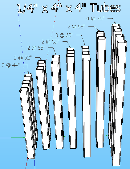
¼” Thick, 4" x 4" Steel Tube
- 3 @ 44"
- 2 @ 52"
- 2 @ 55"
- 2 @ 59"
- 3 @ 60"
- 2 @ 68"
- 4 @ 76"
5/16” Thick, 2 1/2" Dia Steel Tube
- 4 @ 5"
3/8” Thick, 3" x 6" Steel Tube
- 1 @ 45"
- 2 @ 100"
1 7/8" Shaft
- 4 @ 26"
- 1 @ 56"
Parts Fabrication
- The purpose of this section is to prepare the components for final assembly. This includes cutting steel into required lengths and shapes, drilling, welding and shaping as required for final assembly.
- Unless otherwise specified, drill all holes at 13/16" diameter.
- Drill holes through entire tube (ie: through both sides).
- For each tube, measure all holes from one end of tube.
¼” x 4" x 4" Steel Tube
- Verify the following 4" x 4" tubes have already been cut:
- 3 Lower cross members
- Drill holes at 14", 46"
- Rotate 90 degrees, drill holes at 2", 10", 50", 58"
- 2 Bottom Inner North-South members
- Drill holes at 6", 9", 13", 30", 63", 67", 70"
- Rotate 90 degrees, drill holes at 2", 10", 50", 58"
- 2 Bottom Outer North-South members
- Drill holes at 9", 13", 63", 67"
- Rotate 90 degrees, drill holes at 2", 34", 58 1/2" 62", 74"
- 2 Front Vertical members
- Drill holes at 6", 50"
- Rotate 90 degrees, drill holes at 2", 46"
- 2 Middle Vertical members
- Drill holes at 6", 24", 50"
- Rotate 90 degrees, drill holes at 2", 46"
- 2 Rear Vertical members
- Drill holes at 2", 21", 29 1/2", 47 1/2", 54"
- Rotate 90 degrees, drill holes at 6", 50"
- 2 Top North-South members
- Drill holes at 6", 22", 62"
- Rotate 90 degrees, drill holes at 2", 26", 66" and a 2 3/8" hole @ 48" with cutting torch
- 3 Top Cross members
- Drill holes at 6", 38"
- Rotate 90 degrees, drill holes at 2", 42"
Assembly
- Use 6 blocks to support the 3 bottom cross members
- Place the 4 bottom North-South members on bottom cross members, secure loosely with 9 1/2" bolts, washers and lock nuts.
- Align the 4 Vertical members with holes in the lower frame, secure loosely with 9 1/2" bolts, washers and lock nuts.
- Align the 2 North-South members with upper holes in the vertical members, secure loosely with 9 1/2" bolts, washers and lock nuts.
- Align the 3 Upper Cross members with holes in the upper North-South members, secure with 9 1/2" bolts, washers and lock nuts.
- Tighten all bolts / nuts.
