LifeTrac III/Manufacturing Instructions
| LifeTrac / LifeTrac III | 
|
|---|---|
| Home | Research & Development | Build It | User's Manual | Community Feedback | |
| Manufacturing Instructions | BOM | CAD & CAM Files | Additional Resources |
Overview
This page gives you all the information you need to make your LifeTrac III from stock steel and parts.
Please note that the LifeTrac III uses one or two Power Cubes to provide power. Please see the Power Cube Manufacturing Instructions for information on how to manufacture it.
![]() Warning: The LifeTrac design is in development. Some information contained in these pages may be out of date.
Warning: The LifeTrac design is in development. Some information contained in these pages may be out of date.
Documents
Fabrication Report
- File:LifeTrac Fabrication Report 25FEB2012.pdf - This is the latest all-encompassing documentation. It includes the BOM, illustrations, and project steps necessary to build LifeTrac III.
Fabrication Drawings
- LifeTrac3 2D Fab Drawings - Note these drawings are incomplete and not up to standard quality
- CAD & CAM Files
Preparation
Parts Manufacture
- The purpose of this section is to prepare the components for final assembly. This includes cutting steel into required lengths and shapes, drilling, welding and shaping as required for final assembly.
Wanted: Reformat to match format of CEB Parts Fabrication
Steel Cut List
- This list contains instructions for cutting the raw steel into pieces for assembly. Most will require further cuts before being ready for assembly.
- Cut the steel into the following lengths.
- Label and separate cuts by "Step" number so you can easily find cuts for each step during the fabrication stage.
- Note: Item Number and part number refer to CAD information. This is un-necessary if you are following the fabrication steps listed.
Link to printable page.
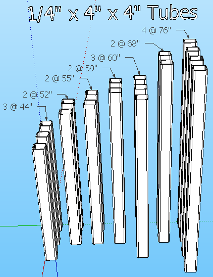
¼” x 4" x 4" Steel Tube
- Verify the following 4" x 4" tubes have already been cut:
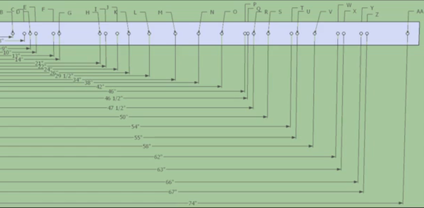
- To simplify hole placement, here is an image of a jig (click to enlarge):
Drilling Tubes
- Unless otherwise specified, drill all holes at 13/16" diameter.
- Drill holes through entire tube (ie: through both sides).
- For each tube, measure all holes from one end of tube.
- 3 Lower cross tubes, 60" long
- Drill holes at 14", 46"
- Rotate 90 degrees, drill holes at 2", 10", 50", 58"
- 2 Bottom Inner North-South tubes, 76" long
- Drill holes at 6", 9", 13", 30", 63", 67", 70"
- Rotate 90 degrees, drill holes at 2", 10", 50", 58"
- 2 Bottom Outer North-South tubes, 76" long
- Drill holes at 9", 13", 63", 67"
- Rotate 90 degrees, drill holes at 2", 34", 58 1/2" 62", 74"
- 2 Front Vertical tubes, 55" long
- Drill holes at 6", 50"
- Rotate 90 degrees, drill holes at 2", 46"
- 2 Middle Vertical tubes, 52" long
- Drill holes at 6", 24", 50"
- Rotate 90 degrees, drill holes at 2", 46"
- 2 Rear Vertical tubes, 59" long
- Drill holes at 2", 21", 29 1/2", 47 1/2", 54"
- Rotate 90 degrees, drill holes at 6", 50"
- 2 Top North-South tubes, 68" long
- Drill holes at 6", 22", 62"
- Rotate 90 degrees, drill holes at 2", 26", 66" and a 2 3/8" hole @ 48" (with cutting torch)
- 3 Top Cross tubes, 44" long
- Drill holes at 6", 38"
- Rotate 90 degrees, drill holes at 2", 42"
Other
These are captured processes from the old nav bar. If removing link from this page please ensure they are added into the R&D somewhere
- Rebar - Bending rebar for treads
Assembly
Wanted: Reorganize to match Power Cube Assembly layout
- Frame - Page on assembling the frame from old nav bar
- Arms - Page on assembling the arms from old nav bar
- Quick Attach Plate
- Hydraulics - Link to hydraulics on Make Projects - no content
Previous Assembly Pictures and Instructions
This is probably accurate but needs to have its own page to keep consistent with the other projects like the CEB Press and the Power Cube.
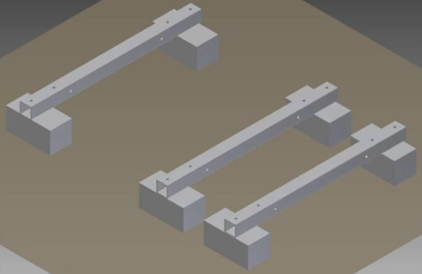
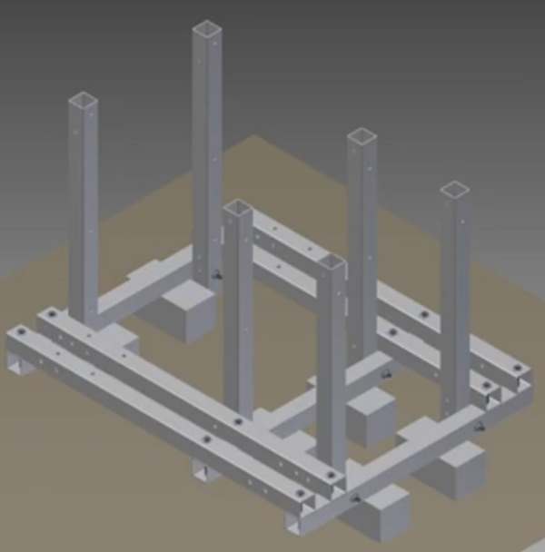
- Use 6 blocks to support the 3 bottom cross members
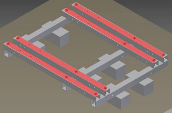
- Place the 4 bottom North-South members on bottom cross members, secure loosely with 9 1/2" bolts, washers and lock nuts.
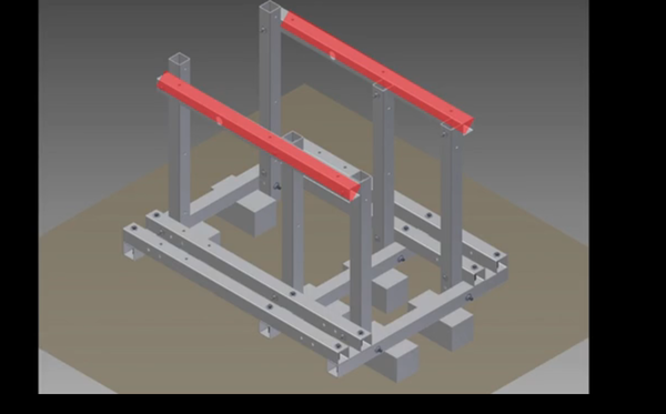
- Align the 6 Vertical members with holes in the lower frame, secure loosely with 9 1/2" bolts, washers and lock nuts.
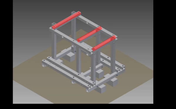
- Align the 2 Top North-South members with upper holes in the vertical members, secure loosely with 9 1/2" bolts, washers and lock nuts.
- Align the 3 Upper Cross members with holes in the upper North-South members, secure with 9 1/2" bolts, washers and lock nuts.
- Tighten all bolts / nuts.
Updates
Wheel Motor Upgrade
Loader Arm Upgrade
BOM
- 2 917-2212 1/2" X 12" 1/2 NPTM X 1/2 NPTM 3500 14.00
- 3 917-2224 1/2" X 24" 1/2 NPTM X 1/2 NPTM 3500 27.00
- 2 917-2260 1/2" X 60" 1/2 NPTM X 1/2 NPTM 3500 30.00
- 1 917-2272 1/2" X 72" 1/2 NPTM X 1/2 NPTM 3500 17.00
- 2 917-22108 1/2" X 108" 1/2 NPTM X 1/2 NPTM 3500 48.00
- 1 917-22120 1/2" X 120" 1/2 NPTM X 1/2 NPTM 3500 26.00
- 1 917-22144 1/2" X 144" 1/2 NPTM X 1/2 NPTM 3500 30.00
- 4 9-1501-8-8 1/2 NPTM x 1/2 NPTF 90 SWIVEL 13.60
- 4 9-1603-8-8-8 1/2 x 1/2 x 1/2 NPTF SWIVEL TEE 32.00
- 4 9-1501-6-8 3/8 NPTM x 1/2 NPTF 90 SWIVEL 15.60
- 2 9-5404-8-8 1/2 NPT HEX NIPPLE 3.30
- 2 9-7710-20 2X20X1.25 DA HYD CYL 1 PINS HVY DUTY 301.90
- 2 9-6401-8-8 SAE 8M TO 1/2" NPTM CONNECTOR 3.50
- 2 9-6901-8-8 SAE 8M x 1/2 NPTF 90 SWIVEL 11.00
- 16 1-2768-187 1.875 DOUBLE SPLIT SHAFT COLLAR 128.00
- Total $: 700.90
____________________________________________________________________________
- Order Recap:
- Total Product $: 700.90
- Net Product$: 700.90
- Shipping: 50.60
- Sales Tax: 0.00
- Insurance : 2.00
- Grand Total: 753.50
