LifeTrac III/Manufacturing Instructions: Difference between revisions
Jump to navigation
Jump to search
Tom Griffing (talk | contribs) |
Tom Griffing (talk | contribs) |
||
| Line 99: | Line 99: | ||
==Parts Fabrication== | ==Parts Fabrication== | ||
* The purpose of this section is to prepare the components for final assembly. This includes cutting steel into required | * The purpose of this section is to prepare the components for final assembly. This includes cutting steel into required | ||
====¼” x 4" x 4" Steel Tube==== | ====¼” x 4" x 4" Steel Tube==== | ||
Revision as of 10:37, 7 November 2011
| LifeTrac III | ||
|---|---|---|
| Home | Research & Development | Bill of Materials | Manufacturing Instructions | User's Manual | User Reviews | 
| |
| ||||||||||||||||||||||||||
Overview
LifeTrac is a low-cost, multipurpose open source tractor. It serves as a workhorse backbone for many of GVCS technologies.
Featuring a modular design and detachable PowerCube units, it has the ability to rapidly switch between a variety of GVCS machines via the QA Plate. The machine is overbuilt with a focus on lifetime design and ease of repair.
Four hydraulic motors provide skid steer power to the wheels, and a unique chain tread system enables navigation of fairly extreme terrain.
Preparation
Safety
- Hearing Protection
- Eye Protection
- Steel Toe Boots
- Welding
- Gloves
- Hood
- Apron/Jacket
Workspace
This section describes the various workspace areas that we have found to be useful in fabricating the LifeTrac. It is provided as a suggestion for preparing your work area.
- Storage: For raw steel and parts
- Cutting Area: For use with cutting torch - Made from non-flammable materials
- Welding Table: Usually steel, suitable for use with arc welder (MIG, TIG, stick, etc)
- Ventilation for cutting / welding areas
Tools
- Welder
- Angle Grinder
- Hand Tools
- Crescent wrench
- Socket set
- Hammer
- Metal Cutting Tools
- Bandsaw
- Chopsaw
- Torch
- Paint Tools
- Gravity Fed Paint Sprayer
- Air compressor
Cut Sheet
- This list contains instructions for cutting the raw steel into pieces for assembly. Most will require further cuts before being ready for assembly.
3/8” Thick, 8" Plate
- 4 @ 12 1/2"
1/2" Thick, 4" Plate
- 6 @ 6"
- 8 @ 4" (cut each diagonally for 16 triangles)
1/2" Thick, 8" Plate
- 4 @ 6"
- 8 @ 10"
1/2" Thick, 10" Plate
- 8 @ 10"
- 4 @ 6 3/4"
1/2" Thick, 12" Plate
- 5 @ 12"
1" Thick, 8" Plate
- 4 @ 4 1/2"
1/2” Thick, 4" x 6" Angle
- 4 @ 6"
¼” Thick, 2 3/8" Dia Steel Tube
- 1 @ 4 1/2"
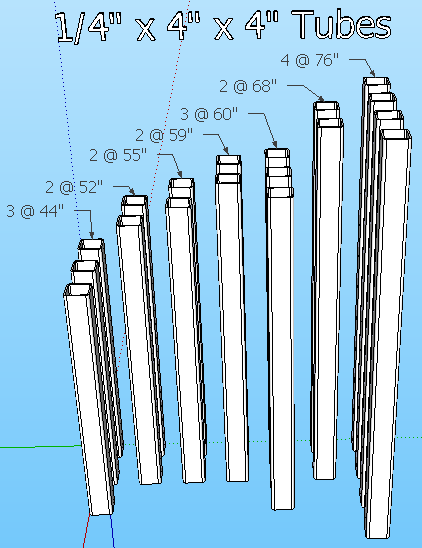
¼” Thick, 4" x 4" Steel Tube
- 3 @ 44"
- 2 @ 52"
- 2 @ 55"
- 2 @ 59"
- 3 @ 60"
- 2 @ 68"
- 4 @ 76"
5/16” Thick, 2 1/2" Dia Steel Tube
- 4 @ 5"
3/8” Thick, 3" x 6" Steel Tube
- 1 @ 45"
- 2 @ 100"
1 7/8" Shaft
- 4 @ 26"
- 1 @ 56"
Parts Fabrication
- The purpose of this section is to prepare the components for final assembly. This includes cutting steel into required
¼” x 4" x 4" Steel Tube
- Verify the following 4" x 4" tubes have already been cut:
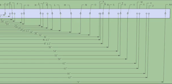
- To simplify hole placement, here is an image of a jig (click to enlarge):
Tube Drilling
- 3 Lower cross tubes, 60" long
- Drill holes at 14", 46"
- Rotate 90 degrees, drill holes at 2", 10", 50", 58"
- 2 Bottom Inner North-South tubes, 76" long
- Drill holes at 6", 9", 13", 30", 63", 67", 70"
- Rotate 90 degrees, drill holes at 2", 10", 50", 58"
- 2 Bottom Outer North-South tubes, 76" long
- Drill holes at 9", 13", 63", 67"
- Rotate 90 degrees, drill holes at 2", 34", 58 1/2" 62", 74"
- 2 Front Vertical tubes, 55" long
- Drill holes at 6", 50"
- Rotate 90 degrees, drill holes at 2", 46"
- 2 Middle Vertical tubes, 52" long
- Drill holes at 6", 24", 50"
- Rotate 90 degrees, drill holes at 2", 46"
- 2 Rear Vertical tubes, 59" long
- Drill holes at 2", 21", 29 1/2", 47 1/2", 54"
- Rotate 90 degrees, drill holes at 6", 50"
- 2 Top North-South tubes, 68" long
- Drill holes at 6", 22", 62"
- Rotate 90 degrees, drill holes at 2", 26", 66" and a 2 3/8" hole @ 48" (with cutting torch)
- 3 Top Cross tubes, 44" long
- Drill holes at 6", 38"
- Rotate 90 degrees, drill holes at 2", 42"
Assembly
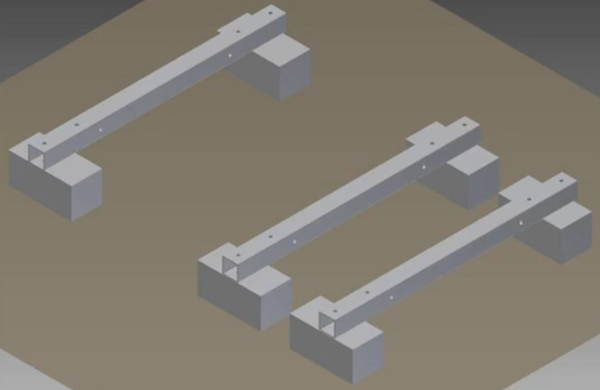
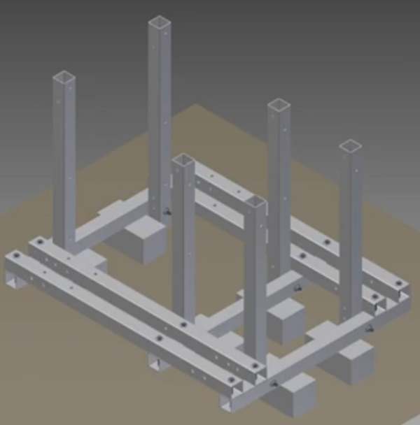
- Use 6 blocks to support the 3 bottom cross members
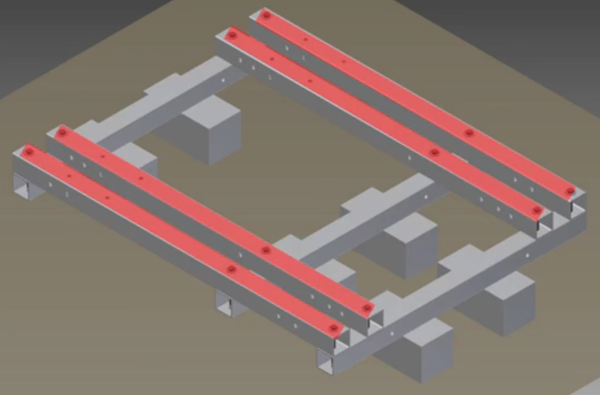
- Place the 4 bottom North-South members on bottom cross members, secure loosely with 9 1/2" bolts, washers and lock nuts.
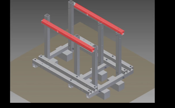
- Align the 6 Vertical members with holes in the lower frame, secure loosely with 9 1/2" bolts, washers and lock nuts.
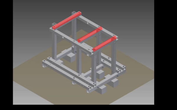
- Align the 2 Top North-South members with upper holes in the vertical members, secure loosely with 9 1/2" bolts, washers and lock nuts.
- Align the 3 Upper Cross members with holes in the upper North-South members, secure with 9 1/2" bolts, washers and lock nuts.
- Tighten all bolts / nuts.
