CEB Press/Research Development/Controller Design: Difference between revisions
| Line 68: | Line 68: | ||
=== Operator Indicators === | === Operator Indicators === | ||
The controller does not require any external operator indicators during normal operation. | |||
The [[CEB_Press/Manufacturing_Instructions/Detroit_Fab_Lab_Solenoid_Driver_v2 |interface board]] provides 7 LEDs which are useful during setup and diagnostics: | |||
* 5 output monitor LEDs, one associated with each solenoid driver channel | |||
* 2 status LEDs, (TBD) | |||
=== Control Processor === | === Control Processor === | ||
== Sequence Logic == | == Sequence Logic == | ||
Revision as of 18:35, 29 December 2011
Operating Cycle
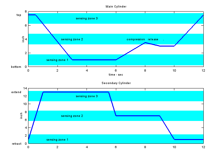
The values on this cycle chart are for illustration and do not represent actual performance
(Plot generated from this Octave plotting script.)
The left of the cycle chart starts with a completed block having just been raised from the chamber, and the drawer already filled with fresh dirt. Subsequently, in sequence,
- The secondary cylinder extends to eject the block
- The main cylinder retracts downward, receiving dirt from the drawer
- The shaker motor operates
- The secondary cylinder retracts to mid-position, closing the chamber
- The main cylinder rises to compress the block; simultaneously dirt is falling from the hopper, refilling the drawer
- The main cylinder retracts slightly
- The secondary cylinder retracts fully, allowing clearance for the block to be ejected
- The main cylinder raises the completed block
The progress of the cycle is controlled on the basis of
- position feedback from the main cylinder travel
- position feedback from the secondary cylinder/drawer travel
- preset time delays
Start-up (Initialization)
TBD
Controller hardware design
Sensors
Although an early prototype controlled machine movements on the basis of timing alone ("open loop" control), this method is not robust against variations in power source flow, fluid viscosity, soil load, and so on. It is essential to use feedback of the machine position in order to get reliable operation.
There are three important positions in the main cylinder stroke
- The bottom position, where soil is received for compression
- The middle position, where soil is compressed
- The top position, where the completed brick is ejected
There are three important positions in the secondary cylinder stroke
- The retracted position, where the finished brick is raised for ejection
- The middle position, where
- soil is loaded from the hopper into the drawer, and
- the brick is compressed by the main cylinder
- The extended position, where the finished brick is ejected to the output tray
There are many approaches to feedback, including a continuous position encoder, a fluid pressure sensor indicating "bottoming out" pressure, etc. The method chosen is simple, robust, and can be adjusted mechanically (rather than requiring a software interface).
In this approach, there is only one sensor for each cylinder, and it is activated three times over the stroke. This is shown as "sensor zone 1", sensor zone 2", and "sensor zone 3" in the cycle illustration above. There is therefore an ambiguity in the sensor output itself: it is impossible to tell which zone is occupied when the sensor signal activates. However, within the operational cycle of the machine, the ambiguity is resolved. For example, when lowering the main cylinder after brick ejection, it is clear that the sensor will first be active in zone3, then inactive, then active in zone 2, then inactive, and finally complete the stroke at zone 1.
The hardware implementation of the sensor is with a stationary Hall-effect device and three magnets on the moving part. The sensor electrical output varies from (TBD) to (TBD) volts as the magnet passes by, and whenever the signal is greater than a threshold of (TBD) volts it is considered "active". Typically each sensor zone is approximately 1 inch (TBD?) wide. Overall, this should be a maintenance-free device: it is a non-contact technique that has no wearing parts and the electrical components are completely encapsulated.
Construction of the Hall-effect sensors is shown at Sensor Unit manufacturing instructions
Alternative sensor implementations are possible, and will be compatible with the controller if they provide a signal which is greater than threshold in each of the sensing zones and less than threshold in between.
Actuators
There are three hydraulic circuits, as described at Hydraulic Design, with five solenoid coils:
- Main cylinder raise (extend) - valve 1 "A" coil
- Main cylinder lower (retract) - valve 1 "B" coil
- Secondary cylinder left (extend) - valve 2 "B" coil
- Secondary cylinder right (retract) - valve 2 "A" coil
- Shaker motor - valve 3 "A" coil
These are 12V DC solenoid coils, controlled by a MOSFET driver board described at Solenoid Driver v2
Operator Controls
The controller does not require any externally accessible operator controls for normal operation.
The interface board includes a reset switch.
Operator Indicators
The controller does not require any external operator indicators during normal operation.
The interface board provides 7 LEDs which are useful during setup and diagnostics:
- 5 output monitor LEDs, one associated with each solenoid driver channel
- 2 status LEDs, (TBD)
