CEB Press/Manufacturing Instructions/Detroit Fab Lab Solenoid Driver v2
Part Information
- This is the official Generation 3 Electronics system for the CEB Press. This displaces the need for an Arduino breakout board in the controller design, reducing both cost and complexity of the controller significantly. This circuit has not yet been field tested extensively under CEB operating conditions. Full control simulation with manual analog signal changes have been a success. Developers are encouraged to build Generation 3 CEB Electronics. Generation 1 and 2 electronics are outdated. See blog post on CEB controller electronics generations.
- Solenoid Driver v2 Etching Images made using Paint.net, edited using GIMP
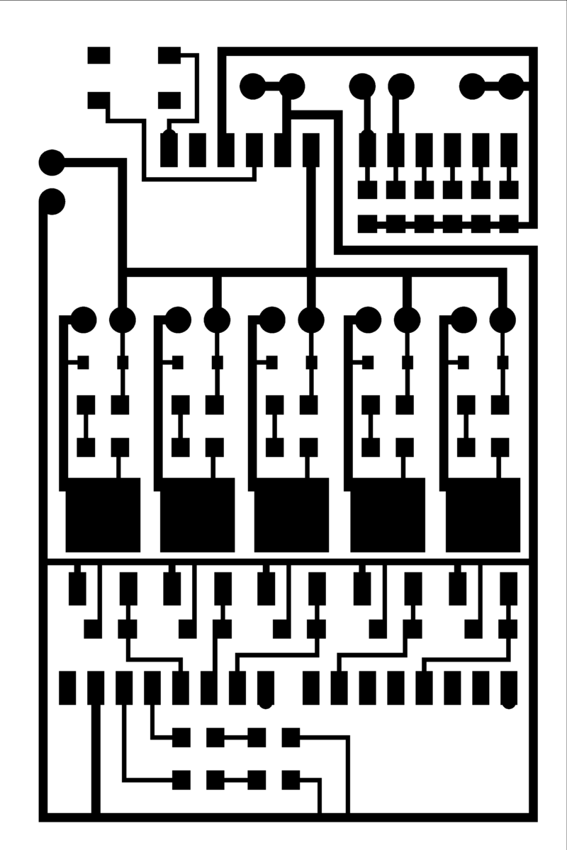
- 2" x 3" Solenoid Driver Image (milling-compatible - [1]
- Video of driver board etching and surface mounting of components using toner transfer method
Tools
- Oxide Remover Solution - Ex. Isopropyl
- Masking Tape
- Etching Solution - Ex. Ferric Chloride
- Toner Removal Solution - Ex. Acetone
- Glass Bowl that fits 3" x 4.5" area dimensions with at least 1" depth
- Paper towel
- Compatible Set of Computer and Laser Printer with Glossy Paper
- Laundry Iron
- Drill Press with Number 58 Twist Drill Bit
- Compatible Set of Soldering Iron, Low-diameter Solder, Flux and Brush, Soldering Stand, and Wet Sponge or Wet Paper Towel
Materials
Steps
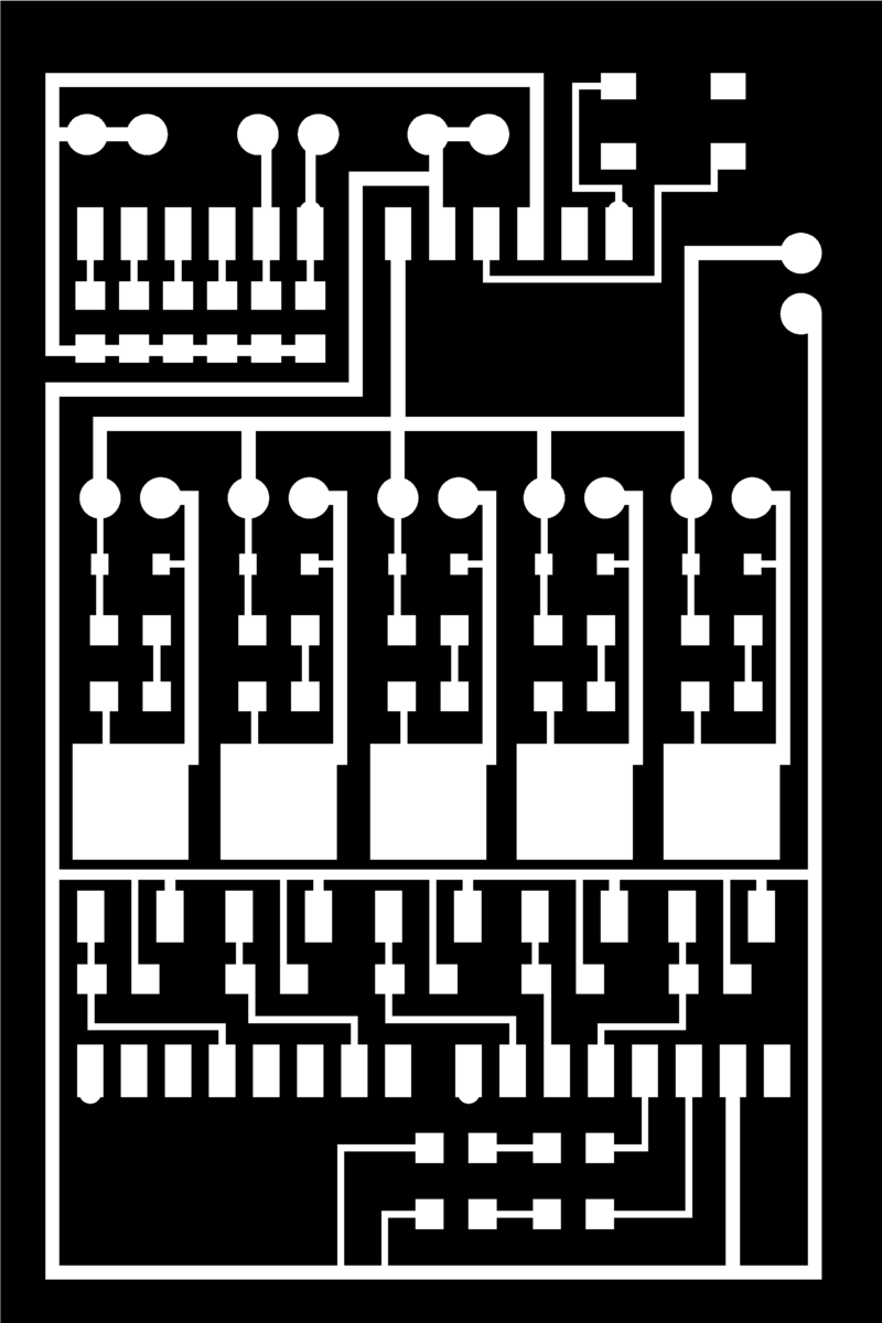
- Etch the copper clad board with the following toner printout at 3" x 4.5" as dimensions
- Drill the etched board at the two rows of small grey squares where the pins would be (28 holes) and all grey circles of where the screw terminals would be (18 holes) as shown in the following diagram
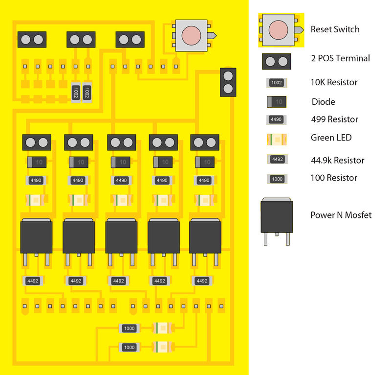
- Surface-mount solder the etched and drilled copper clad board with the complete board diagram above. The 6 POS Headers go in the top drilled holes, and the 8 POS Headers go in the bottom holes.
Assistance
- OSE Forum - http://forum.opensourceecology.org/discussion/520/replication-assistance-detroit-board
- Tutors
OLD
- 2" x 3" Solenoid Driver Image
- 2" x 3" Flipped Colour-Reversed Solenoid Driver Image (etching-compatible)
Upgrades
1
Field testing at Factor e Farm in 2011 has shown that twigs and rocks can jam the soil loading drawer if these are not crushed by the scissor action of the drawer. In the case of a jam, we uploaded the CEB testing code interface to move the drawer and get it unstuck - by computer control via USB cable. This is time consuming, so the next iteration should include manual bypass toggles on the controller board itself, so the user can move the drawer manually as needed. This applies to both the primary and secondary cylinder.
To do this, a simple toggle switch such as the reset switch should be placed between the 5V power and the digital output (d9 or d10) pin corresponding to the left (ejection) motion of the secondary cylinder. This is not necessary for the main cylinder, which has 20 tons of force. This is also not necessary for the right motion of the secondary cylinder, since such motion is already present upon power cycling of the controller.
Implementation
Do we need just a connection to be closed between 5V and the d9 or d10? An?y resistors in between?
- how about a "garage door" button. if its running and you push it it will stop. push it again it goes in reverse. push it again it stops. push it again it continues along again. if we had a button that connected one of the digital channels to the ground would that be sufficient to trigger the software? we could put a button on the board or have a terminal wired to an external box button. --Dorkmo 04:15, 3 December 2011 (CET)
Resolved
The initialization sequence which moves the secondary cylinder to the left in addition to the right addresses the issue of jams, without the solenoid manual button on the controller.
2
For full manual testing of hydraulics without using a control computer, 5 of these manual toggles should be applied, one for each hydraulic channel.
Standalone Version for use in other projects


