LifeTrac IV/Research Development/Carrying capacity: Difference between revisions
Jump to navigation
Jump to search
| Line 2: | Line 2: | ||
This page provides information for the approximate carrying capacity before vehicle tipping. Additional information is desired to determine structural strength when loaded. Operating load is defined as 50% of the tipping load. | This page provides information for the approximate carrying capacity before vehicle tipping. Additional information is desired to determine structural strength when loaded. Operating load is defined as 50% of the tipping load. | ||
=Analysis= | ==C of G Analysis== | ||
{{Wanted| Formulas for calculating the | [[Image:lifetracCOG.jpg|800px]] | ||
==Force Distribution Analysis== | |||
{{Wanted| Formulas for calculating the force distribution as a function of arm angle}} | |||
[[file:Sideview2.PNG|thumb]] | [[file:Sideview2.PNG|thumb]] | ||
* Assume symmetric | * Assume symmetric along center plane | ||
* [[:File:LifeTrac_sideview.doc |LifeTrac image in MS Word file]] | * [[:File:LifeTrac_sideview.doc |LifeTrac image in MS Word file]] | ||
* Basically what we need is an understanding between carried load CofG, vehicle CofG, arm pivot location, hydraulic cylinder mounted location and the front wheel which acts as the point to tip around. | * Basically what we need is an understanding between carried load CofG, vehicle CofG, arm pivot location, hydraulic cylinder mounted location and the front wheel which acts as the point to tip around. | ||
Revision as of 04:16, 27 January 2012
Overview
This page provides information for the approximate carrying capacity before vehicle tipping. Additional information is desired to determine structural strength when loaded. Operating load is defined as 50% of the tipping load.
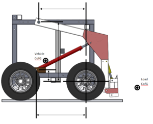
C of G Analysis
Force Distribution Analysis
Wanted: Formulas for calculating the force distribution as a function of arm angle
- Assume symmetric along center plane
- LifeTrac image in MS Word file
- Basically what we need is an understanding between carried load CofG, vehicle CofG, arm pivot location, hydraulic cylinder mounted location and the front wheel which acts as the point to tip around.
- Keep everything in x-y coordinate system for the initial static analysis and then provide the formula as a function of load location as it arcs around the loader arm pivot point at the top of the frame.
- The end goal is to have a formula that can be applied to any design
- Add whatever additional considerations are required to make the analysis more accurate
- Please provide definitions of variables used, easily understood diagram and formulas
- If uploading to wiki is a problem, please email data to Mike Apostol directly

