CNC Torch Table 2/Control Overview: Difference between revisions
m (→Test mule) |
m (→Test mule) |
||
| Line 114: | Line 114: | ||
* First test [[User:ChuckH|ChuckH]] 02:51, 24 September 2012 (CEST) | * First test [[User:ChuckH|ChuckH]] 02:51, 24 September 2012 (CEST) | ||
** single coil per phase, steppernug configured for 50% of full current, full current = 2.5A, so phase current = 1.25A. | |||
** power source: 12V | |||
** single motor connected to channel A | |||
** Success! G-code command "X5" issued through gcodesender causes motor to move a few rotations. Miller Time :) | |||
==Detail== | ==Detail== | ||
Revision as of 01:01, 24 September 2012
Overview
Endstops
To implement the endstops, we are modifying the GRBL file (firmware for the Arduino AVR328P) and flashing it onto the Arduino. This process requires one to understand GRBL, pinouts of Arduino, AVR chip, AVRdude uploader. GCC is used to complile c to hexadecimal.
The source code can be found at_______________ (An OSE fork on grbl github - who is making this?)
Schematic
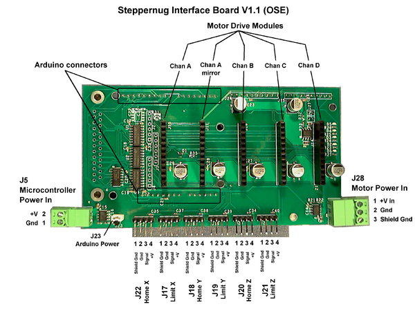
Arduino controller pin connections
Cross reference: StepperNug vs GRBL defaults (v0.7 Master, config.h)
| StepperNug Intfc V1.1 | GRBL default (ref) | |||||||
| Function | Schematic Pin |
Port | Bit | Arduino Pin |
Port | Bit | Arduino Pin |
Equiv. Function |
| Clk A | 5 | B | 5 | 13 | D | 2 | 2 | Step X |
| Dir A | 6 | B | 4 | 12 | D | 5 | 5 | Dir X |
| Clk B | 7 | B | 3 | 11 | D | 3 | 3 | Step Y |
| Dir B | 8 | B | 2 | 10 | D | 6 | 6 | Dir X |
| Clk C | 9 | B | 1 | 9 | D | 4 | 4 | Step Z |
| Dir C | 10 | B | 0 | 8 | D | 7 | 7 | Dir Z |
| Home X | 11 | D | 7 | 7 | B | 1 | 9 | Limit X |
| Home Y | 12 | D | 6 | 6 | B | 2 | 10 | Limit Y |
| Home Z | 13 | D | 5 | 5 | B | 3 | 11 | Limit Z |
| Enable | 14 | D | 4 | 4 | B | 0 | 8 | Disable |
| Spindle | 15 | D | 3 | 3 | B | 4 | 12 | Spindle enable |
| Home/Limit Interrupt |
16 | D | 2 | 2 | ||||
| B | 5 | 13 | Spindle Dir | |||||
Physical
Software
grbl
I am starting with grbl v0.7 Master branch from https://github.com/grbl/grbl . ChuckH 02:36, 24 September 2012 (CEST)
grbl requires an appropriate config.h file and a patch to the stepper-enable polarity in order to work with steppernug.
Relevant parts of config.h (pin assignments):
// Define pin-assignments
#define STEPPING_DDR       DDRB
#define STEPPING_PORT      PORTB
#define X_STEP_BIT         5  // Uno Digital Pin 13
#define Y_STEP_BIT         3  // Uno Digital Pin 11
#define Z_STEP_BIT         1  // Uno Digital Pin 9
#define X_DIRECTION_BIT    4  // Uno Digital Pin 12
#define Y_DIRECTION_BIT    2  // Uno Digital Pin 10
#define Z_DIRECTION_BIT    0  // Uno Digital Pin 8

#define STEPPERS_DISABLE_DDR    DDRD
#define STEPPERS_DISABLE_PORT   PORTD
#define STEPPERS_DISABLE_BIT    4  // Uno Digital Pin 4

#define LIMIT_DDR     DDRD
#define LIMIT_PIN     PIND
#define X_LIMIT_BIT   7  // Uno Digital Pin 7
#define Y_LIMIT_BIT   6  // Uno Digital Pin 6
#define Z_LIMIT_BIT   5  // Uno Digital Pin 5

#define SPINDLE_ENABLE_DDR DDRD
#define SPINDLE_ENABLE_PORT PORTD
#define SPINDLE_ENABLE_BIT 3  // Uno Digital Pin 3

#define SPINDLE_DIRECTION_DDR DDRD
#define SPINDLE_DIRECTION_PORT PORTD
#define SPINDLE_DIRECTION_BIT 1  // Uno Digital Pin 13
(Note: I assigned SPINDLE_DIRECTION to an unused pin as a quick hack.)
To reverse the polarity of the stepper enable pin (another quick hack), I exchanged these two lines in stepper.c:
	Line 104:   STEPPERS_DISABLE_PORT &= ~(1<<STEPPERS_DISABLE_BIT);
	Line 120:   STEPPERS_DISABLE_PORT |= (1<<STEPPERS_DISABLE_BIT);
G-code generation
For initial testing from Windows, gcodesender is a useful tool, as described here.
Test mule
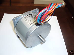
I am not building a torch table but I need a breadboard "mule" to test software functionality. I purchased four of these 34-frame steppers.
These are split-winding (8 wire) motors so each phase can be driven either series or parallel. Each individual coil seems to be rated 3V, 1.7amp.
- First test ChuckH 02:51, 24 September 2012 (CEST)
- single coil per phase, steppernug configured for 50% of full current, full current = 2.5A, so phase current = 1.25A.
- power source: 12V
- single motor connected to channel A
- Success! G-code command "X5" issued through gcodesender causes motor to move a few rotations. Miller Time :)
Detail
so the interrupt works on INT0, active low. i'm not debouncing it, unless you want me to, but maybe that's not advised for end stop interrupts.
in my notes, i have that we want to use INTB (aka INT1) for spindle control. (i recall we also said something about that being an input for "home," but my notes are poor on this point; can you can explain what functionality you want here, Darren?)
anyway, by default, spindle enable is pb4, and spindle direction is pb5, which map to pins 8 & 9 respectively. but we're using those two pins for Z axis control currently. so we'd need another pin than INTB, at the least, tho i'm a fan of using the defaults personally.
regarding doing something with that INT0 interrupt, i.e. disabling the motors (and something with pin4, which would reenable them): is the idea that after an end stop is hit, the interrupt is thrown, the motors stop and G code stopped, and then the user manually moves the heads back to some home location, and then presses a button to reneable the motors? or do you want this interrupt to work as if was interpreting a particular gcode ( M2 comes to mind).
Zeroing
The x axis (long axis) has 2 stepper motors. These are typically coupled.
For zeroing, the x axis needs to decouple - so if we get the x axis out of parallel, we can jog the x axes back into parallel by hitting the end stops.


