LifeTrac IV/Research Development/Carrying capacity: Difference between revisions
(Tipping load calculations & Calculations of the static force on the joint of the arm added) |
(Case 2: tractor is used for pushing objects) |
||
| Line 35: | Line 35: | ||
L_JA_WL: The distance between the joint of the arm and the c of g of the pallet <br /> | L_JA_WL: The distance between the joint of the arm and the c of g of the pallet <br /> | ||
θ: The angle between the L_JA_WL and the horizontal <br /> | θ: The angle between the L_JA_WL and the horizontal <br /> | ||
g: The gravity of Earth ( g = 9.81 m/(sec^2) ) | |||
RFW is the summation of the reaction forces applied to the two front wheels. I do not include the weight of the arm in the weight of the vehicle, because the position of the center of gravity of the arm changes while the arm rises. The same might be considered for the hydraulic cylinders, in more detailed calculations. | RFW is the summation of the reaction forces applied to the two front wheels. I do not include the weight of the arm in the weight of the vehicle, because the position of the center of gravity of the arm changes while the arm rises. The same might be considered for the hydraulic cylinders, in more detailed calculations. | ||
Balance of | Balance of moments: <br /> | ||
L_WV*WV – L_RRW*RRW – L_WL*WL – L_WA*WA = 0 | L_WV*WV*g – L_RRW*RRW – L_WL*WL*g – L_WA*WA*g = 0 | ||
where, <br /> | where, <br /> | ||
| Line 50: | Line 51: | ||
For any WL, the reaction force on each wheel of the rear axis is the half of RRW, where: <br /> | For any WL, the reaction force on each wheel of the rear axis is the half of RRW, where: <br /> | ||
RRW = (L_WV*WV – L_WL*WL – L_WA*WA)/L_RRW | RRW = (L_WV*WV*g – L_WL*WL*g – L_WA*WA*g)/L_RRW | ||
The balance of forces implies that: <br /> | The balance of forces implies that: <br /> | ||
– RRW – RFW + WV + WL + WA = 0 | – RRW – RFW + WV*g + WL*g + WA*g = 0 | ||
Therefore, the reaction force on each wheel of the front axis is 0.5*RFW, where: <br /> | Therefore, the reaction force on each wheel of the front axis is 0.5*RFW, where: <br /> | ||
RFW = WV + WL + WA – RRW | RFW = WV*g + WL*g + WA*g – RRW*g | ||
'''Warning:''' Tipping load calculations, for the case that the vehicle is decelerating or climbing down a slope, might be also necessary. | |||
===Calculations of the static force on the joint of the arm=== | ===Calculations of the static force on the joint of the arm=== | ||
'''Warning:''' This is a rough static load calculation that needs verification. Additional dynamic calculations should be considered. | |||
====Case 1: tractor is used for lifting objects==== | |||
[[file:Lifetrac_IV_static_forces_on_the_joint.bmp]] | [[file:Lifetrac_IV_static_forces_on_the_joint.bmp]] | ||
| Line 76: | Line 83: | ||
L_JHV_JHA: The current length of the hydraulic cylinder (from joint JHV to joint JHA) <br /> | L_JHV_JHA: The current length of the hydraulic cylinder (from joint JHV to joint JHA) <br /> | ||
The force R_JHA is always in the direction of the axis of the hydraulic cylinder. That is because the joints of the cylinder cannot transmit | The force R_JHA is always in the direction of the axis of the hydraulic cylinder. That is because the joints of the cylinder cannot transmit moments at the direction of z. | ||
(90deg – ω – α) is the angle between the L_JA_JHV and the L_JHV_JHA (i.e. the angle that has as a tip the joint JHV and as ends the joints JHA and JA). | (90deg – ω – α) is the angle between the L_JA_JHV and the L_JHV_JHA (i.e. the angle that has as a tip the joint JHV and as ends the joints JHA and JA). | ||
| Line 85: | Line 92: | ||
ω = arccos(sin(φ)*L_JA_JHA/L_JHV_JHA) – α | ω = arccos(sin(φ)*L_JA_JHA/L_JHV_JHA) – α | ||
Balance of the | Balance of the moments applied at the arm (calculated at the position of JA): <br /> | ||
L_JA_JHV* sin(90deg – ω – α)*R_JHA – (L_JA + L_WL)*WL – (L_JA + L_WA)*WA = 0 => <br /> | L_JA_JHV* sin(90deg – ω – α)*R_JHA – (L_JA + L_WL)*WL*g – (L_JA + L_WA)*WA*g = 0 => <br /> | ||
L_JA_JHV*cos(ω+α)*R_JHA – (L_JA + L_WL)*WL – (L_JA + L_WA)*WA = 0 | L_JA_JHV*cos(ω+α)*R_JHA – (L_JA + L_WL)*WL*g – (L_JA + L_WA)*WA*g = 0 | ||
Thus, the force applied from the hydraulic cylinders to the arm is: <br /> | Thus, the force applied from the hydraulic cylinders to the arm is: <br /> | ||
R_JHA = ( (L_JA + L_WL)*WL + (L_JA + L_WA)*WA )/( L_JA_JHV*cos(ω+α)) | R_JHA = ( (L_JA + L_WL)*WL*g + (L_JA + L_WA)*WA*g )/( L_JA_JHV*cos(ω+α) ) | ||
The vehicle is symmetric, so each of the two cylinders applies a force to the arm that equals to 0.5*R_JHA. | The vehicle is symmetric, so '''each of the two cylinders applies a force''' to the arm that equals to 0.5*R_JHA. | ||
The balance of forces at the vertical direction gives: | The balance of forces at the vertical direction gives: | ||
R_JAy = R_JHA*sin(ω) – WL – WA | R_JAy = R_JHA*sin(ω) – WL*g – WA*g | ||
The balance of forces at the horizontal direction gives: | The balance of forces at the horizontal direction gives: | ||
| Line 106: | Line 113: | ||
R_JA = ( (R_JAx)^2 + (R_JAy)^2 )^0.5 | R_JA = ( (R_JAx)^2 + (R_JAy)^2 )^0.5 | ||
This force is distributed equivalently to the two joints between the arm and the frame of the vehicle. Thus, 0.5*R_JA is applied to each joint. If there is no bending on this cylindrical joint, the maximum shear stress is: | This force is distributed equivalently to the two joints between the arm and the frame of the vehicle. Thus, 0.5*R_JA is applied to each joint. '''If there is no bending''' on this cylindrical joint, the maximum shear stress is: | ||
τ_shear = (4/3)*F/A | τ_shear = (4/3)*F/A | ||
| Line 117: | Line 124: | ||
This equivalent stress must be less than (<) the tensile strength of the material of the pin divided by a safety factor. | This equivalent stress must be less than (<) the tensile strength of the material of the pin divided by a safety factor. | ||
In reality the problem has three dimensions. Depending on the suspensions of the vehicle and other structural features, '''additional | '''Warning:''' In reality the problem has three dimensions. Depending on the suspensions of the vehicle and other structural features, '''additional moments''' at the direction of x might be applied to the joints. | ||
[[file:Lifetrac_IV_joint_load_example.bmp|x330px]] | |||
For instance, let’s assume that the holes of the tube where the pin fits are not identical (i.e. only one hole and the pin are in contact). At the pin of the joint that is illustrated in picture (β), only shear force is applied, and its stress (τ_shear) can be calculated as above. On the other hand, at the pin of the joint that is illustrated in picture (α) shear force and bending moment are applied. The stress from the shear force is calculated as above. The stress from the bending moment is:<br/> | |||
σ_bending = (M/I)*r | |||
where, M=F*L <br /> | |||
is the applied moment at the pin, F is the force applied at the end of the pin and L is its length (distance from the start of the pin to the point that F is applied). <br /> | |||
I = (pi/4)*r^4 <br /> | |||
is the second moment of inertia of the cross section of the pin and r is its radius. | |||
In this case, which both shear force and bending moment are applied, the equivalent tensile stress is calculated using the equation below. <br /> | |||
σ_total = ( σ_bending^2 + 4 * τ_shear^2 )^0.5 | |||
====Case 2: tractor is used for pushing objects==== | |||
[[file:lifetrac_IV_static_forces_on_the_joint_case_2.bmp]] | |||
T_max: The maximum torque of the motor that is on each wheel.<br /> | |||
r_wheel: The radius of the wheels. <br /> | |||
F can be the reaction force that is applied when the tractor pushes the objects. At the picture above it is assumed that the contact point, which force F is applied, is close to pallet c of g. However, similar equations can be solved wherever the contact point is. <br /> | |||
If each wheel has a driving motor then: <br /> | |||
F = 4* T_max* r_wheel <br /> | |||
Balance of the moments applied at the arm (calculated at the position of JA): <br /> | |||
L_JA_JHV*cos(ω+α)*R_JHA – (L_ JA + L_ WL)*WL*g – (L_ JA + L_ WA)*WA*g – L_JA_WL*sin(θ)*F= 0 <br /> | |||
Thus, the force applied from the hydraulic cylinders to the arm is: <br /> | |||
R_JHA = ( (L_ JA + L_ WL)*WL*g + (L_ JA + L_ WA)*WA*g + L_JA_WL*sin(θ)*F )/( L_JA_JHV*cos(ω+α) ) <br /> | |||
The vehicle is symmetric, so '''each of the two cylinders applies a force''' to the arm that equals to 0.5*R_JHA. <br /> | |||
The balance of forces at the vertical direction gives: <br /> | |||
R_JAy = R_JHA*sin(ω) – WL*g – WA*g <br /> | |||
The balance of forces at the horizontal direction gives: <br /> | |||
R_JAx = R_JHA*cos(ω) – F <br /> | |||
The total force R_JA is: <br /> | |||
R_JA = ( (R_JAx)^2 + (R_JAy)^2 )^0.5 <br /> | |||
This force is distributed equivalently to the two joints between the arm and the frame of the vehicle. Thus, 0.5*R_JA is applied to each joint. | |||
====Case 3: impact==== | |||
Force F could also be considered as an impact force of several g (x in number). In this case F = x*g*(WV + WA). | |||
=See also= | |||
*[[LifeTrac IV Loader Lift Capacity]] | *[[LifeTrac IV Loader Lift Capacity]] | ||
*http://www.nstmop.psu.edu/tasksheets/4.12%20Tractor%20Stability.pdf | *http://www.nstmop.psu.edu/tasksheets/4.12%20Tractor%20Stability.pdf | ||
Revision as of 17:11, 3 April 2013
Overview
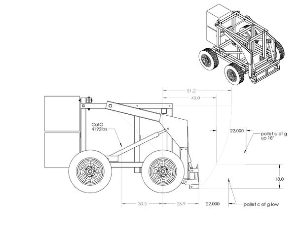
This page provides information for the approximate carrying capacity before vehicle tipping. Additional information is desired to determine structural strength when loaded. Operating load is defined as 50% of the tipping load.
C of G Analysis
- Weight is approximate to +/- 200lbs
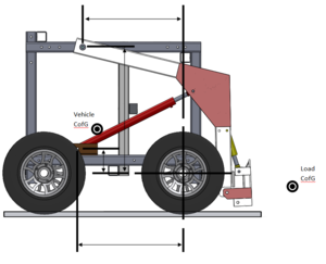
- Tipping load is calculated by summing the moments around the front axle
Force Distribution Analysis
Wanted: Formulas for calculating the force distribution as a function of arm angle
- Assume symmetric along center plane
- LifeTrac image in MS Word file
- Basically what we need is an understanding between carried load CofG, vehicle CofG, arm pivot location, hydraulic cylinder mounted location and the front wheel which acts as the point to tip around.
- Keep everything in x-y coordinate system for the initial static analysis and then provide the formula as a function of load location as it arcs around the loader arm pivot point at the top of the frame.
- The end goal is to have a formula that can be applied to any design
- Add whatever additional considerations are required to make the analysis more accurate
- Please provide definitions of variables used, easily understood diagram and formulas
- If uploading to wiki is a problem, please email data to Mike Apostol directly
Tipping load calculations
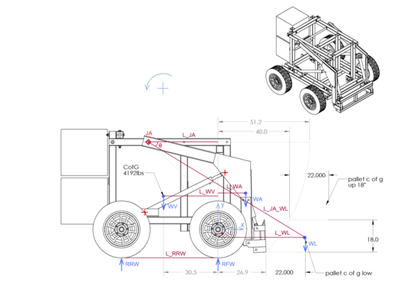
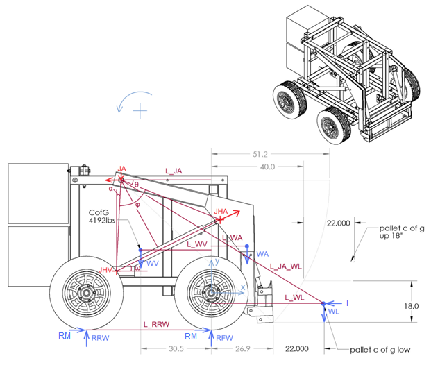
WL: Weight of load (pallet)
WA: Weight of arm
WV: Weight of vehicle (without the weight of arm)
RFW: Reaction force at the front wheels
RRW: Reaction force at the rear wheels
L_WL: The distance between the c of g of the pallet (where WL is applied) and the vector y
y: The vertical vector that passes through the axis of the front wheels
JA: The position of the joints that support the arm on the frame of the vehicle
L_JA_WL: The distance between the joint of the arm and the c of g of the pallet
θ: The angle between the L_JA_WL and the horizontal
g: The gravity of Earth ( g = 9.81 m/(sec^2) )
RFW is the summation of the reaction forces applied to the two front wheels. I do not include the weight of the arm in the weight of the vehicle, because the position of the center of gravity of the arm changes while the arm rises. The same might be considered for the hydraulic cylinders, in more detailed calculations.
Balance of moments:
L_WV*WV*g – L_RRW*RRW – L_WL*WL*g – L_WA*WA*g = 0
where,
L_WL = L_JA_WL*cos(θ) – L_JA
Similar equation can be found for L_WA. Negative value of the L_WA implies that the c of g of the arm lies on the left side of the vector y.
The vehicle is tipping when RRW=0. Thus the tipping load is:
WL_tipping = (L_WV*WV – L_WA*WA)/L_WL
For any WL, the reaction force on each wheel of the rear axis is the half of RRW, where:
RRW = (L_WV*WV*g – L_WL*WL*g – L_WA*WA*g)/L_RRW
The balance of forces implies that:
– RRW – RFW + WV*g + WL*g + WA*g = 0
Therefore, the reaction force on each wheel of the front axis is 0.5*RFW, where:
RFW = WV*g + WL*g + WA*g – RRW*g
Warning: Tipping load calculations, for the case that the vehicle is decelerating or climbing down a slope, might be also necessary.
Calculations of the static force on the joint of the arm
Warning: This is a rough static load calculation that needs verification. Additional dynamic calculations should be considered.
Case 1: tractor is used for lifting objects
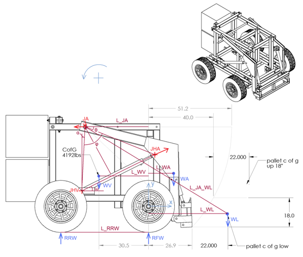
JA: The joint between the arm and the frame of the vehicle
JHV: The joint between the hydraulic cylinder and the frame of the vehicle
JHA: The joint between the hydraulic cylinder and the arm
R_JAy: The force applied from the vehicle to the arm, at vertical direction
R_JAx: The force applied from the vehicle to the arm, at horizontal direction
R_JHA: The force applied from the hydraulic cylinders to the arm
R_JHAy: The vertical component of the force applied from the hydraulic cylinders to the arm
R_JHAx: The horizontal component of the force applied from the hydraulic cylinders to the arm
ω: The angle between the direction of the hydraulic cylinder and the horizontal
L_JA_JHV: The distance between the positions of the joint JA and the joint JHV
L_JA_JHA: The distance between the positions of the joint JA and the joint JHA
L_JHV_JHA: The current length of the hydraulic cylinder (from joint JHV to joint JHA)
The force R_JHA is always in the direction of the axis of the hydraulic cylinder. That is because the joints of the cylinder cannot transmit moments at the direction of z.
(90deg – ω – α) is the angle between the L_JA_JHV and the L_JHV_JHA (i.e. the angle that has as a tip the joint JHV and as ends the joints JHA and JA).
sin(90deg – ω – α)/L_JA_JHA = sin(φ)/L_JHV_JHA =>
cos(ω+α)/L_JA_JHA = sin(φ)/L_JHV_JHA =>
cos(ω+α) = sin(φ)*L_JA_JHA/L_JHV_JHA =>
ω = arccos(sin(φ)*L_JA_JHA/L_JHV_JHA) – α
Balance of the moments applied at the arm (calculated at the position of JA):
L_JA_JHV* sin(90deg – ω – α)*R_JHA – (L_JA + L_WL)*WL*g – (L_JA + L_WA)*WA*g = 0 =>
L_JA_JHV*cos(ω+α)*R_JHA – (L_JA + L_WL)*WL*g – (L_JA + L_WA)*WA*g = 0
Thus, the force applied from the hydraulic cylinders to the arm is:
R_JHA = ( (L_JA + L_WL)*WL*g + (L_JA + L_WA)*WA*g )/( L_JA_JHV*cos(ω+α) )
The vehicle is symmetric, so each of the two cylinders applies a force to the arm that equals to 0.5*R_JHA.
The balance of forces at the vertical direction gives:
R_JAy = R_JHA*sin(ω) – WL*g – WA*g
The balance of forces at the horizontal direction gives:
R_JAx = R_JHA*cos(ω)
The total force R_JA is:
R_JA = ( (R_JAx)^2 + (R_JAy)^2 )^0.5
This force is distributed equivalently to the two joints between the arm and the frame of the vehicle. Thus, 0.5*R_JA is applied to each joint. If there is no bending on this cylindrical joint, the maximum shear stress is:
τ_shear = (4/3)*F/A
where F = 0.5*R_JA is the applied force and A = pi*r^2 is the cross-sectional area of the pin (that has radius r) of the joint. pi is 3.14.
The equivalent tensile stress is:
σ_total = 2*τ_shear
This equivalent stress must be less than (<) the tensile strength of the material of the pin divided by a safety factor.
Warning: In reality the problem has three dimensions. Depending on the suspensions of the vehicle and other structural features, additional moments at the direction of x might be applied to the joints.
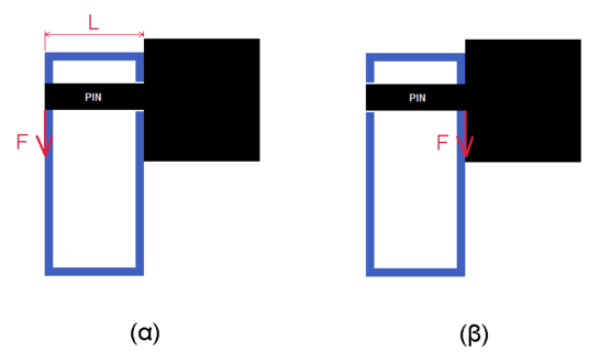
For instance, let’s assume that the holes of the tube where the pin fits are not identical (i.e. only one hole and the pin are in contact). At the pin of the joint that is illustrated in picture (β), only shear force is applied, and its stress (τ_shear) can be calculated as above. On the other hand, at the pin of the joint that is illustrated in picture (α) shear force and bending moment are applied. The stress from the shear force is calculated as above. The stress from the bending moment is:
σ_bending = (M/I)*r
where, M=F*L
is the applied moment at the pin, F is the force applied at the end of the pin and L is its length (distance from the start of the pin to the point that F is applied).
I = (pi/4)*r^4
is the second moment of inertia of the cross section of the pin and r is its radius.
In this case, which both shear force and bending moment are applied, the equivalent tensile stress is calculated using the equation below.
σ_total = ( σ_bending^2 + 4 * τ_shear^2 )^0.5
Case 2: tractor is used for pushing objects
T_max: The maximum torque of the motor that is on each wheel.
r_wheel: The radius of the wheels.
F can be the reaction force that is applied when the tractor pushes the objects. At the picture above it is assumed that the contact point, which force F is applied, is close to pallet c of g. However, similar equations can be solved wherever the contact point is.
If each wheel has a driving motor then:
F = 4* T_max* r_wheel
Balance of the moments applied at the arm (calculated at the position of JA):
L_JA_JHV*cos(ω+α)*R_JHA – (L_ JA + L_ WL)*WL*g – (L_ JA + L_ WA)*WA*g – L_JA_WL*sin(θ)*F= 0
Thus, the force applied from the hydraulic cylinders to the arm is:
R_JHA = ( (L_ JA + L_ WL)*WL*g + (L_ JA + L_ WA)*WA*g + L_JA_WL*sin(θ)*F )/( L_JA_JHV*cos(ω+α) )
The vehicle is symmetric, so each of the two cylinders applies a force to the arm that equals to 0.5*R_JHA.
The balance of forces at the vertical direction gives:
R_JAy = R_JHA*sin(ω) – WL*g – WA*g
The balance of forces at the horizontal direction gives:
R_JAx = R_JHA*cos(ω) – F
The total force R_JA is:
R_JA = ( (R_JAx)^2 + (R_JAy)^2 )^0.5
This force is distributed equivalently to the two joints between the arm and the frame of the vehicle. Thus, 0.5*R_JA is applied to each joint.
Case 3: impact
Force F could also be considered as an impact force of several g (x in number). In this case F = x*g*(WV + WA).
