Hydraulic Connection Diagram Standards: Difference between revisions
Jump to navigation
Jump to search
No edit summary |
No edit summary |
||
| Line 1: | Line 1: | ||
Main point of hydraulic diagram is that it allows one to move on 3 points: (1) component design, (2) readily ability for work to be reviewed; (3) ability to source components readily, including BOM generation. Further - (4) a large hydraulics design can be worked on in real time by several people via Google Docs to create a Master Design - in [[One Day]]. | |||
To draw a hydraulic diagram: | To draw a hydraulic diagram: | ||
#use a vector graphics program such as Google Docs Drawings [www.drive.google.com www.drive.google.com] | #use a vector graphics program such as Google Docs Drawings [www.drive.google.com www.drive.google.com] | ||
| Line 6: | Line 8: | ||
#label the specifications of hydraulic components and fittings | #label the specifications of hydraulic components and fittings | ||
#use [[OSE Title Block]] | #use [[OSE Title Block]] | ||
#List all parts below the diagram with links to sources. | |||
[[Image:Ostrac_hydraulics.jpg|x300px]] | |||
[[Image:CEBhydbuild.jpg|x300px]] | |||
[[Image:Hydtankdiagram.jpg|x300px]] | |||
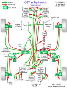
#Sample Conceptual Diagram without images of parts. Sufficient but does not provide the builder with a visual understanding of parts used. | #Sample Conceptual Diagram without images of parts. Sufficient but does not provide the builder with a visual understanding of parts used. | ||
Revision as of 23:40, 15 June 2013
Main point of hydraulic diagram is that it allows one to move on 3 points: (1) component design, (2) readily ability for work to be reviewed; (3) ability to source components readily, including BOM generation. Further - (4) a large hydraulics design can be worked on in real time by several people via Google Docs to create a Master Design - in One Day.
To draw a hydraulic diagram:
- use a vector graphics program such as Google Docs Drawings [www.drive.google.com www.drive.google.com]
- paste in component images
- link connections via lines
- use simple drawings to elucidate context
- label the specifications of hydraulic components and fittings
- use OSE Title Block
- List all parts below the diagram with links to sources.
- Sample Conceptual Diagram without images of parts. Sufficient but does not provide the builder with a visual understanding of parts used.
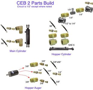
- Example with pictures. Best example for physical build clarity.
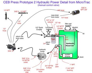
- Example with pictures and specifications, without pictures of fittings.


