Power Cube/Manufacturing Instructions/Fabrication June 2011: Difference between revisions
(→Frame) |
(→Frame) |
||
| Line 94: | Line 94: | ||
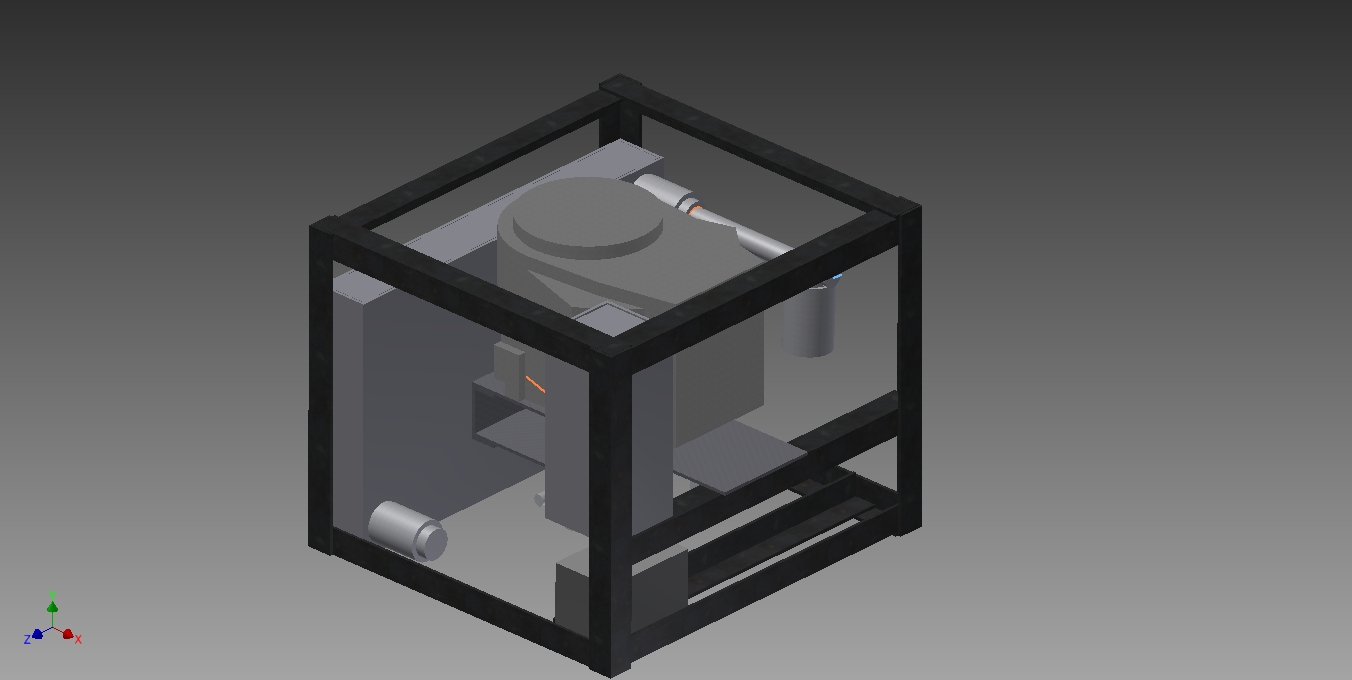
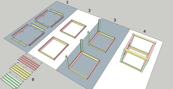
The frame is assembled in halves, and tack/welded in place. A completed frame should look like like this. | The frame is assembled in halves, and tack/welded in place. A completed frame should look like like this. | ||
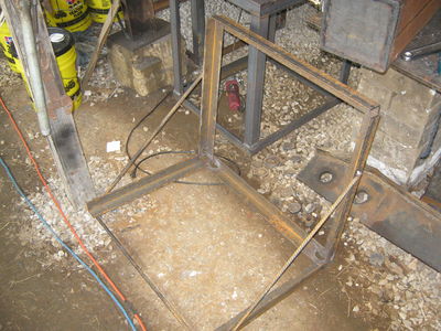
[[Image:PowerCubeFramePhoto.jpg]] | [[Image:PowerCubeFramePhoto.jpg|600px]] | ||
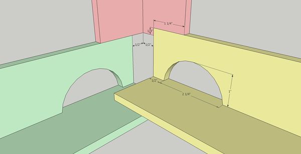
[[Image:PowerCubeFrameSketch.jpg]] | [[Image:PowerCubeFrameSketch.jpg|600px]] | ||
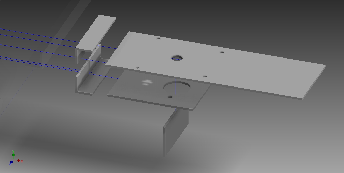
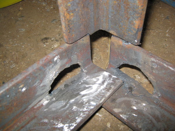
[[Image:PowerCubeFrameCloseup.jpg]] | [[Image:PowerCubeFrameCloseup.jpg|600px]] | ||
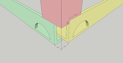
Note the overlap order. Short angles (green) on the outside. | Note the overlap order. Short angles (green) on the outside. | ||
Revision as of 05:42, 13 June 2011
![]() This page is currently under construction and might undergo drastic changes within a short span of time.
This page is currently under construction and might undergo drastic changes within a short span of time.
Power Cube 4.0 Construction
Here's how to replicate our Powercube 4.0 design. Keep in mind that this the powercube is still at the prototype stages and designs are likely to change.
BOM
| Name | Quantity | Dimensions | Type |
| ENGINE ASSEMBLY | 1 | ||
| Engine | 1 | ||
| Mounting Plate - Hydraulic Motor | 1 | 8"x10"x1/4" | Flat |
| Connector Plate | 1 | 8"x3.75"x1/4" | Flat |
| Mounting Angle | 2 | 8"x(2"x1/4") | Angle |
| Engine Mount Plate | 1 | 8"x23"x1/4" | Flat |
| Lovejoy Coupler | 1 | 2.5"x2.25" | Cylinder |
| Hydraulic Motor | 1 | ||
| Gas Tank | 1 | 14"x6"x6" | Box |
| FUEL FILTER ASSEMBLY | 1 | ||
| Fuel Filter Fitting | 1 | ||
| Fuel Filter | 1 | 3.5"x5" | Cylinder |
| FRAME ASSEMBLY | 1 | 24"x27.5"x30" | Box |
| 24" Angle | 4 | 24"x(2"x1/4") | Angle |
| 27" Angle | 4 | 27"x(2"x1/4") | Angle |
| 29" Angle | 6 | 29"x(2"x1/4") | Angle |
| HYDRAULIC TANK ASSEMBLY | 1 | 19"x29"x4" | Box |
| Hydraulic Tank Plates | 2 | 19"x29"x1/4" | Flat |
| Flat - Hydraulic Sides | 2 | 19"x3.5"x1/4" | Flat |
| Flat - Hydraulic Bottom/Top | 2 | 3.5"x28.5"x1/4" | Flat |
| Battery | 1 | 5"x6"x7.5" | Box |
| Hydraulic Mount | 2 | 4.75"x3" | Cylinder |
Total Metal to Purchase
| Type | Width | Thickness | Total Length (rounded up) |
| Angle | 2" | 1/4" | 400" |
| Plate | 19" | 1/4" | 60" |
| Plate | 8" | 1/4" | 40" |
| Plate | 6" | 1/4" | 12" |
| Plate | 3.5" | 1/4" | 100" |
| Tube | 6" | 1/4" | 14" |
Frame
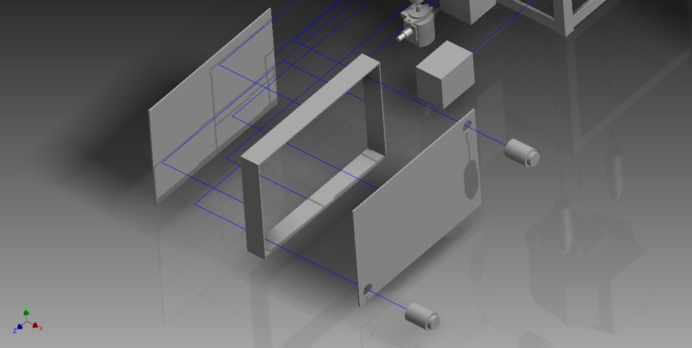
The Power Cube 4.0 (as of this prototype at least) is not actually a strict cube. But more of a lopsided box.) The longest dimensions are on the side (left to right), while the shortest dimension is up/down. See below.
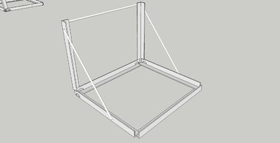
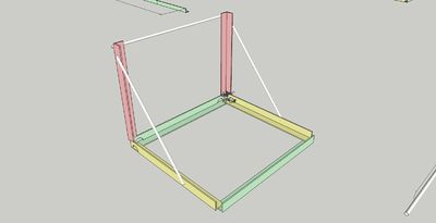
The frame is assembled in halves, and tack/welded in place. A completed frame should look like like this.
Note the overlap order. Short angles (green) on the outside.
Assembly
Mounting Assembly
Hydraulic Tank Assembly
Final
Jig (optional)
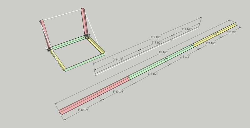
The jig is an optional piece of fabrication equipment that can be very useful to have should you be creating several power cubes concurrently. The materials for the cube are assembled in the jig in half sections and tacked and welded in place.
Materials List
Total Length 14' Angle (2"x1/4") 7'2" Rebar (1/2")
Cut List
| Type | Length | Dimensions | Quantity | Color |
| Angle | 22" | (2"x1/4") | 2 | (red) |
| Angle | 26" | (2"x1/4") | 2 | (yellow) |
| Angle | 29" | (2"x1/4") | 2 | (green) |
| Rebar | 30.5" | (1/2") | 1 | |
| Rebar | 27" | (1/2") | 2 |
Assembly of the Jig is fairly straight forward. Tack and weld the pieces in place.
Be sure to note the overlapping order and the notch made at the bottom of the 1'10 1/4" piece (red). Torch holes in the corners below the frame as seen above. This allows room for the welding torch to get to the PowerCube while welding.
Also note that the corners are offset 3/4" (1/2" measured on the interior), to give room for the cube to sit snugly in the frame (and a convenient gap for welding the corners.)
Tack weld the two shorter rebar sections at roughly a 45 degree angle on the sides. Add a long rebar section to span the gap. Precision is not as important with these, they are more there for stability.
With any luck, you'll have your jig, ready to crank out Power Cubes with!
