Induction Furnace Power Electronics Design Rationale and Specification: Difference between revisions
Jump to navigation
Jump to search
(→Links) |
|||
| Line 2: | Line 2: | ||
=Design Rationale= | =Design Rationale= | ||
This specification is for the power electronics and controls component only - other components being the heating coil with cooling system, and the melt chamber proper. It includes feedback on temperature and maximum-power-delivery tracking to the melt. This is a frequency and power level selectable power supply with automatic feedback for controlling an optimum melt sequence. | |||
The concept is to design a stackable power supply where power supply modules may be stacked - just like the stackability of the [[Stackable Inverter]]. | |||
=Specifications= | =Specifications= | ||
Revision as of 04:40, 20 January 2012
See also [[1]]
Design Rationale
This specification is for the power electronics and controls component only - other components being the heating coil with cooling system, and the melt chamber proper. It includes feedback on temperature and maximum-power-delivery tracking to the melt. This is a frequency and power level selectable power supply with automatic feedback for controlling an optimum melt sequence.
The concept is to design a stackable power supply where power supply modules may be stacked - just like the stackability of the Stackable Inverter.
Specifications
- Rated Power output: 12.5 KW (running from a 2 ton battery bank of 3 forklift batteries at 24v each for testing purposes)
- Output Voltage: 300 V or whatever is required for an efficient melt
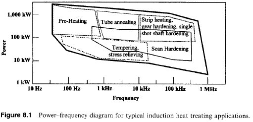
- Output Frequency: 1 KHz - 30 KHz
- Input voltage: 24 VDC or 72 VDC
- Input current: 500 A or 170 A
- Duty cycle: 100%
- Efficiency: >90%
Particulars
- IGBT Technology and control
- Temperature controllable
