Bearing Selection
The instructions on this page are intended to guide the designer through the process of selecting bearings that are appropriate in type and size for its intended purpose and load condition.
- The selection of bearings includes the following steps (which are described in further detail on this page):
Step 1) Define load condition
Step 2) Select bearing type
Step 3) Select bearing arrangement
Step 4) Dimension bearing
Step 5) Select bearing housing design
Step 1) Define load condition
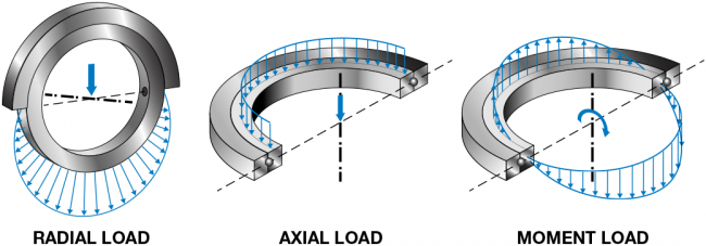
Determine the direction of the forces that the bearing is exposed to.
Step 2) Select bearing type
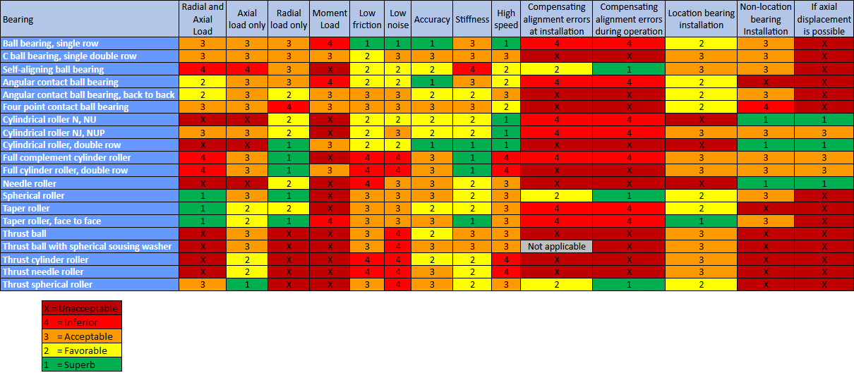
The table below shows level of suitability of different bearing types for different conditions.
This section is based on a table found in SKF handbooks and on the Engineers Edge website.
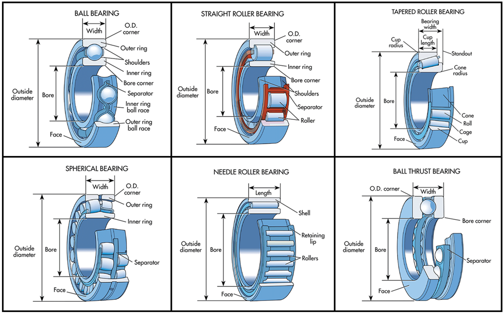 Image source: https://www.machinedesign.com/learning-resources/whats-the-difference-between/article/21831901/whats-the-difference-between-bearings
Step 3) Select bearing arrangement
More than one bearing can be used at each end of an axle. If so, their arrangement should be appropriate for the load condition. There are three basic bearing arrangements:
- Back to back
- Face to face
- Tandem
These arrangements can also be combined.
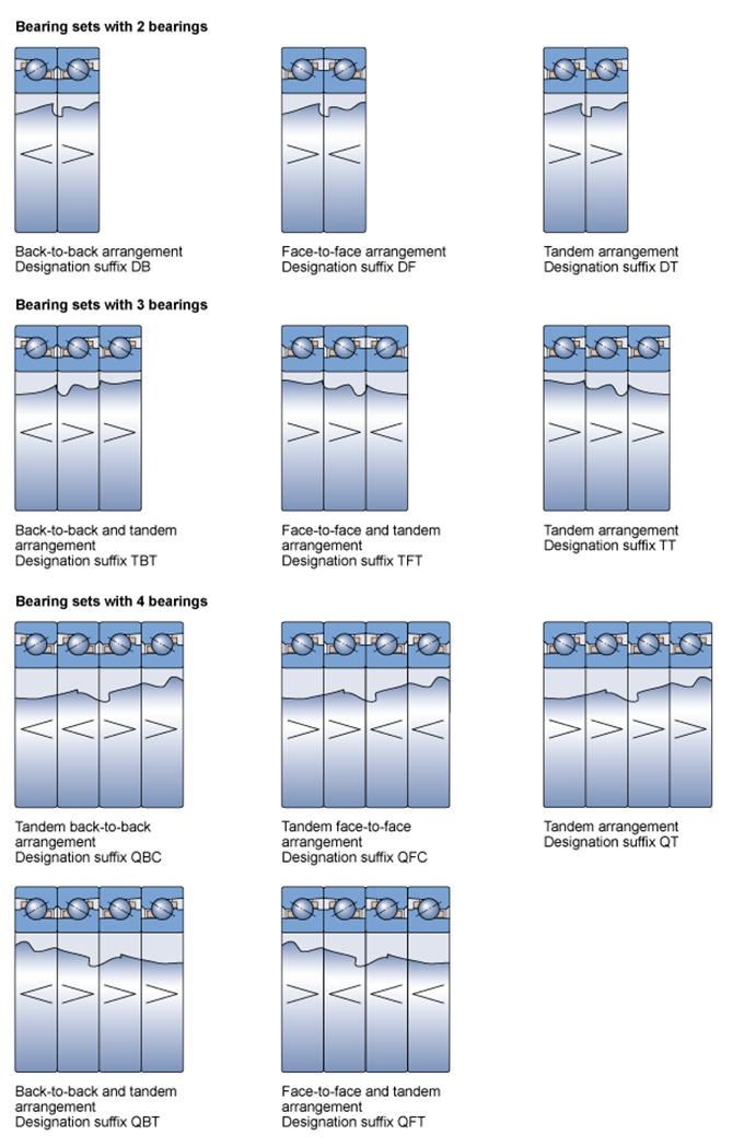
Back-to-back arrangement
In a back-to-back arrangement, the load lines diverge along the bearing axis. Axial loads acting in both directions can be accommodated, but only by one bearing or bearing set in each direction. Bearings mounted back-to-back provide a relatively rigid bearing arrangement. The wide span between bearing effective centres makes this arrangement particularly well suited to support moment loads."
Face-to-face arrangement
In a face-to-face arrangement, the load lines converge along the bearing axis. Axial loads acting in both directions can be accommodated, but only by one bearing or bearing set in each direction. The shorter span between effective bearing centres makes face-to-face arrangements less suitable to support moment loads compared to bearings in a back-to-back arrangement."
Tandem arrangement
The use of a tandem arrangement provides increased axial and radial load carrying capacity compared to a single bearing. In a tandem arrangement, the load lines are parallel so that radial and axial loads are shared. The bearing set can only accommodate axial loads acting in one direction. If axial loads act in both directions, or if combined loads are present, additional bearing(s) adjusted against the tandem arrangement must be added."
Examples
Universally matchable single direction bearings can be arranged in various ways depending on the stiffness and load requirements of the application. The possible arrangements are shown in the image, including the applicable designation suffixes for matched sets. If misalignment cannot be avoided between the bearing positions, face-to-face bearing arrangements are recommended. They are less sensitive to misalignment than back-to-back bearing arrangements. Combinations of tandem arrangements with back-to-back or face-to-face arrangements are usually selected to maximize the stiffness or load carrying capacity of a bearing set in a particular direction. This is the case, for example, when extended, preloaded, vertical or overhung screw drives must be supported."
This section is based on information listed on www.SKF.com and in SKF handbooks.
Step 4) Dimension bearing
This section describes the steps for dimensioning a bearing.
4.1) Access a bearing catalog and identify bearing
Identify a bearing that corresponds to the following:
- the Bearing type that was selected in Step 2.
- an Inner diameter (aka. Bore diameter) that corresponds to the diameter of the axle.
4.2) Calculate Axial load (Fa) and Radial load (Fr)
Some load cases only have a radial load, some only have axial load and some have a combination of axial and radial load.
4.3) Determine the Equivalent dynamic bearing load (P)
Depending on the load case the formula for P will vary;
P = F
when the load is constant in magnitude and direction and acts radially on a radial bearing or axially and centrically on a thrust bearing.
P = Fa
for certain thrust bearings that can only accommodate pure axial loads, such as thrust ball bearings and cylindrical and needle roller thrust bearings, provided that the load acts centrically.
P = XFr + YFa
if a bearing is loaded with simultaneously acting radial load Fr and axial load Fa that are constant in magnitude and direction
where
P equivalent dynamic bearing load [kN]
Fr actual radial bearing load [kN]
Fa actual axial bearing load [kN]
X radial load factor for the bearing
Y axial load factor for the bearing.
P = Fr + Y Fa
for tapered roller bearings and spherical roller bearings.
where
P equivalent dynamic bearing load [kN]
Fr actual radial bearing load [kN]
Fa actual axial bearing load [kN]
Y axial load factor for the bearing.
P = Fr
for cylindrical roller bearings
where
P = equivalent dynamic bearing load [kN]
Fr = actual radial bearing load [kN]
4.4) Determine the value for p-constant
The value of the constant p will depend on the bearing type;
p = 3 for ball bearings
p = 1/3 for roller bearings
p = 4 for pure line contact
4.5) Determine the value for the Dynamic load rating C
The value for the Dynamic load rating (C) is listed by the manufacturer or the designer.
Select a bearing from a product catalog and note its C-value.
Input the C-value into the bearing lifetime formula along with the values for n, P, and p.
If this calculated lifetime (L10h) is lower than the desired lifetime, you need to try with another bearing with a higher C-value.
If the calculated lifetime is higher than the desired lifetime, you can select a bearing with a lower C-value. The calculated lifetime should be at least as high as the desired lifetime.
4.6) Calculate bearing lifetime in hours
L10h = (10^6 / 60n) * ((C/P)^p)
where
L10h = bearing lifetime in hours
n = revolutions per minute
C = dynamic load rating (this value is listed by the manufacturer or the designer)
P = Equivalent dynamic bearing load
p = a constant depending on bearing type.
( Nominal bearing lifetime is just L10 = (C/P)^p. It has a 90% reliability.)
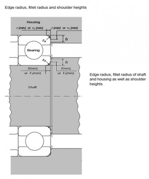
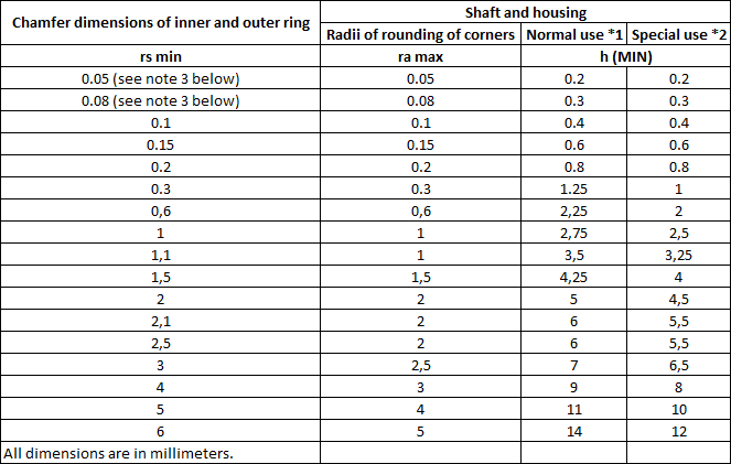
Step 5. Select bearing housing
The baring housing, aka known as bearing holder, is the component that supports the bearing.
Note: all dimensions are in millimeters.
Other considerations
Consider listing values (such as C-value) for bearings that are designed and listed in the Bearing Part Library.
Consider making a bearing selection tool (as an assembly with multiple equation-driven configurations)in FreeCAD.
Internal Links
Bearing Part Library Machine elements Bearing designation
