CNC Torch Table 2/Control Overview
Overview
Endstops
To implement the endstops, we are modifying the GRBL file (firmware for the Arduino AVR328P) and flashing it onto the Arduino. This process requires one to understand GRBL, pinouts of Arduino, AVR chip, AVRdude uploader. GCC is used to complile c to hexadecimal.
The source code can be found at_______________ (An OSE fork on grbl github - who is making this?)
Schematic
Arduino controller pinout
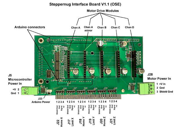
Cross reference: StepperNug vs GRBL defaults (v0.7 Master, config.h)
| StepperNug Intfc V1.1 | GRBL default (ref) | |||||||
| Function | Schematic Pin |
Port | Bit | Arduino Pin |
Port | Bit | Arduino Pin |
Equiv. Function |
| Clk A | 5 | B | 5 | 13 | D | 2 | 2 | Step X |
| Dir A | 6 | B | 4 | 12 | D | 5 | 5 | Dir X |
| Clk B | 7 | B | 3 | 11 | D | 3 | 3 | Step Y |
| Dir B | 8 | B | 2 | 10 | D | 6 | 6 | Dir X |
| Clk C | 9 | B | 1 | 9 | D | 4 | 4 | Step Z |
| Dir C | 10 | B | 0 | 8 | D | 7 | 7 | Dir Z |
| Home X | 11 | D | 7 | 7 | B | 1 | 9 | Limit X |
| Home Y | 12 | D | 6 | 6 | B | 2 | 10 | Limit Y |
| Home Z | 13 | D | 5 | 5 | B | 3 | 11 | Limit Z |
| Enable | 14 | D | 4 | 4 | B | 0 | 8 | Disable |
| Spindle | 15 | D | 3 | 3 | B | 4 | 12 | Spindle enable |
| Home/Limit Interrupt |
16 | D | 2 | 2 | ||||
| B | 5 | 13 | Spindle Dir | |||||
Physical
Software
G-code prep
DXF_to_G-code_Conversion_Tutorial
Nesting software would be useful. Example commercial product here. Anything open source?
Correction for torch cut kerf width ("cutter compensation" in CNC lingo) needed. G40/G41 but grbl does not interpret these.
Gctrl(cross-platform), gcodesender(Windows). Other options for gcode streaming here.
grbl
I am starting with grbl v0.8 "edge" branch forked from https://github.com/grbl/grbl at https://github.com/chuck-h/grbl/tree/edge . ChuckH 09:19, 24 September 2012 (CEST)
grbl requires an appropriate config.h file and a patch to the stepper-enable polarity in order to work with StepperNug.
Relevant parts of config.h (pin assignments):
// Define pin-assignments
#define STEPPING_DDR       DDRB
#define STEPPING_PORT      PORTB
#define X_STEP_BIT         5  // Uno Digital Pin 13
#define Y_STEP_BIT         3  // Uno Digital Pin 11
#define Z_STEP_BIT         1  // Uno Digital Pin 9
#define X_DIRECTION_BIT    4  // Uno Digital Pin 12
#define Y_DIRECTION_BIT    2  // Uno Digital Pin 10
#define Z_DIRECTION_BIT    0  // Uno Digital Pin 8

#define STEPPERS_DISABLE_DDR    DDRD
#define STEPPERS_DISABLE_PORT   PORTD
#define STEPPERS_DISABLE_BIT    4  // Uno Digital Pin 4
#define STEPPERS_DISABLE_INVERT    // Logic low out for disable (e.g. steppernug)

#define LIMIT_DDR     DDRD
#define LIMIT_PIN     PIND
#define X_LIMIT_BIT   7  // Uno Digital Pin 7
#define Y_LIMIT_BIT   6  // Uno Digital Pin 6
#define Z_LIMIT_BIT   5  // Uno Digital Pin 5

#define SPINDLE_ENABLE_DDR DDRD
#define SPINDLE_ENABLE_PORT PORTD
#define SPINDLE_ENABLE_BIT 3  // Uno Digital Pin 3

#define SPINDLE_DIRECTION_DDR DDRD
#define SPINDLE_DIRECTION_PORT PORTD
#define SPINDLE_DIRECTION_BIT 1  // Uno Digital Pin 13
(Note: I assigned SPINDLE_DIRECTION to an unused pin as a quick hack.)
To reverse the polarity of the stepper enable pin, I added the STEPPERS_DISABLE_INVERT flag (above) and changed stepper.c to honor it (lines 104, 124).
Test mule
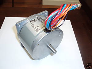
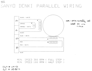
I am not building a torch table but I need a breadboard "mule" to test software functionality. I purchased four of these 34-frame steppers for $10 each.
These are split-winding (8 wire) motors so each phase can be driven either series or parallel. Each individual coil seems to be rated 3V, 1.7amp.
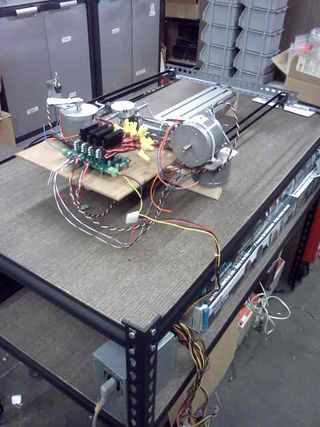
Got my "test mule" put together. Checking out homing functions. ChuckH 04:47, 14 October 2012 (CEST)
Detail
so the interrupt works on INT0, active low. i'm not debouncing it, unless you want me to, but maybe that's not advised for end stop interrupts.
in my notes, i have that we want to use INTB (aka INT1) for spindle control. (i recall we also said something about that being an input for "home," but my notes are poor on this point; can you can explain what functionality you want here, Darren?)
anyway, by default, spindle enable is pb4, and spindle direction is pb5, which map to pins 8 & 9 respectively. but we're using those two pins for Z axis control currently. so we'd need another pin than INTB, at the least, tho i'm a fan of using the defaults personally.
regarding doing something with that INT0 interrupt, i.e. disabling the motors (and something with pin4, which would reenable them): is the idea that after an end stop is hit, the interrupt is thrown, the motors stop and G code stopped, and then the user manually moves the heads back to some home location, and then presses a button to reneable the motors? or do you want this interrupt to work as if was interpreting a particular gcode ( M2 comes to mind).
Limits and Homing
Dual-motor homing
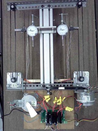
The x axis (long axis) has 2 stepper motors. In the steppernug system, these have separate driver modules which receive identical step, direction, and enable signals.
For zeroing, the x axis needs to decouple - so if we get the x axis out of parallel, we can jog the x axes back into parallel by hitting their home switches independently. Steppernug supports this by allowing the Arduino to control a gate which blocks step pulses to the second driver module; in this condition the second motor will freeze and only the first motor will move. There is no provision for moving the second motor without moving the first, but that function is not required for the homing algorithm.
Axis sequence
- We will home the Z axis to its upper position first, just in case there are obstructions to clear during the X and Y axis homing.
- X and Y axes will do their initial fast moves to find home simultaneously (overlapped homing) to save time.
- The dual-X-axis precision home maneuver will be performed.
- The Y precision home movement will be performed.
Limit and home switch configuration
Unconfirmed proposal at this time ChuckH 23:42, 20 October 2012 (CEST)
Each axis has two switches: a limit switch and a home switch.
- The limit switch is activated at *either* end of travel. Its function is to protect against machine damage.
- It will cause all axis movement to stop, the torch to be shut off, and any other "safe shutdown" operation to be performed.
- The limit switch could be hit if the program erroneously commands the tool to move beyond the edge of the table
- The limit switch could also be hit if the torch table loses step (e.g. by hitting an obstruction) and subsequently performs a movement which takes it to the edge of the table
- The limit switch may be implemented as two physical switches wired in parallel, or the machine construction may permit a single switch to be used.
- Repeatable precision of actuation point is not very critical.
- This function is especially important if the table is expected to do automated cutting without constant human supervision.
- The home switch transitions between inactive and active at a point partway through the legal travel of the machine.
- For example, it might be active at the negative end of travel, and go inactive after 6 inches of movement.
- The home switch is used only for locating a repeatable "zero position" when the machine is powered on (or when recovering from lost steps)
- Note that the logical "machine zero" may be placed at any programmed position relative to the physical home switch.
- Repeatable precision may be important
- For the dual-motor axis, to establish accurate squareness
- For all axes, if any fixed fixturing is used for repeat "production style" operations
- By construction, the home switch is active at one end of travel and inactive at the other
- This allows the machine to know which end of travel it is at in the event the limit switch is activated
- This, in turn, allows the machine to permit recovery movement from the limit condition back into legal travel, while ignoring a command to go further into the limit zone.
There is an alternative switch configuration which places individual limit switches at the positive and negative limits of legal travel. However the configuration above is preferred because it supports faster homing and simpler control logic. Specifically:
- The substantial distance between the end of travel and the home switch location gives the machine overtravel room to do a controlled stop from high speed: maximum slewing speed can be used during initial homing.
- Home switch placement can minimize the typical startup time.
- If an axis is usually parked near one end of travel, the home switch can be placed there
- If the axis position on startup is random, placing the home switch in the center of travel will minimize the average seek time.
- The "safety shutdown" limit-switch function can be always active, and is independent of homing
- The alternative approach requires logically repurposing a limit switch as home switch during home operations
Switch Types
The steppernug interface provides 5V power to sensor switches so either electronic or mechanical switches are easily accommodated.
- Mechanical microswitches are simple and effective.
- A Hall switch (e.g. this) is rugged but its position precision is probably only suitable for limits, not home switches.
- An optical interrupter (e.g. Sharp GP1A75EJ000F) can give precisely repeatable homing.
Torch control
During cutting, an oxyfuel cutting torch is literally burning the steel with a blast of oxygen; most of the heat comes from oxiding the iron. However to start a new cut ("piercing") you must preheat the steel, relying on the acetylene or LPG for heat. After the steel is red hot you boost the oxygen flow and make the cut. We will want an oxygen-rated solenoid valve controlled by the steppernug. ("Oxygen-rated" mostly means the valve is thoroughly cleaned of all oil or flammable solvents that tend to explode on contact with pure oxygen.)
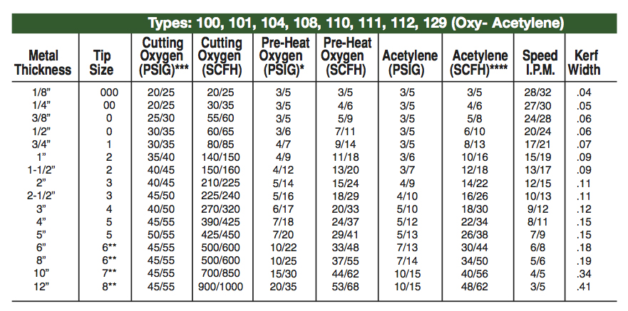
Recommendations from Victor:
