Rob Beddingfield Log
Jump to navigation
Jump to search
Thu Aug 10, 2013
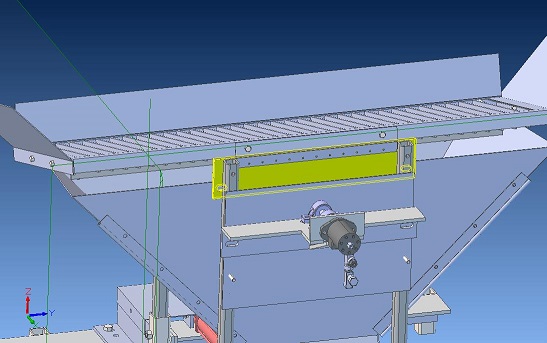
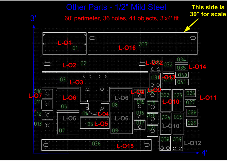
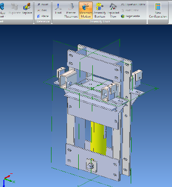
- I'm not sure how to place items L-O15 and L-O16, see pic below as to my guess (yellow part), but it appears that these new parts are wider than the hopper supports,I'm sure I'm missing something.
- I'm not sure how parts L-O12 and L-O14 are placed to make the valve mount, maybe someone has a picture.
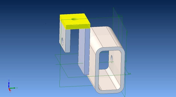
- I may have placed item L-O7 in the wrong place, see pic below (yellow part)
Thu Aug 8, 2013
- MADE 3D MODEL - CAM CLAMP ASSY
- HAVE QUESTIONS ABOUT SENSOR CLAMPS
- HAVE QUESTIONS ABOUT VALVE MOUNTING CLAMPS
- NEED PICTURES OF ALL THREE INCLUDING CAM CLAMPS
TUE, 6 Aug
- CEB V SOIL SHAKER 3D MODEL
MON, 5 Aug
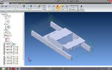
- CEB V Hopper Supports 3d model
SAT, 4 Aug
- CEB V Arm assemblies 3d model
THU, 1 Aug
- CEB V drawer
Wed, 30 Jul
- CEB V frame - modified model for frame to reflect cnc cut parts.
- Finished core assembly, drawer assembly next
Mon, 29 Jul
- CEB V frame - modified model for frame to reflect cnc cut parts.
- still need to assemble top flange assembly
- Christmas_Gift_to_the_World
