Open Source Stepper Motor Controller
Main > Digital Fabrication > RepLab Tools
See also Stepper Motor
Introduction
See Open Source Stepper Motor Controller Problem Statement as a start.
Stepper motors are the simplest drive for moderate precision motion control applications (such as CNC plasma cutting). They provide the best price:performace for low to moderate mechanical power (<200W) at low to moderate RPM (<500 RPM). There is no open source stepper driver, AFAIK. This project will fill that need.
Concept
The output of this project will be a family of general purpose electronic drivers for a variety of electromechanical actuators. The first of them will be a stepper motor driver. With the appropriate alternative firmware (embedded software) the same hardware might be used as a servo driver for a brush-DC servo. With a modified output stage we could drive brushless DC or AC servos, or linear motors.
Design Rationale
Adaptability is good. Software is usually easier than hardware. Microprocessors are cheap. Simple circuits are better than complicated ones (other things being equal).
We keep the circuit simple and general, and we implement the control algorithm in software. We can tweak it most easily that way, and even replace it with something totally different.
This design should give good performance, excellent versatility, good replicability, and moderate cost.
Block Diagram and Modules
Major functional units:
- Computational logic. An Arduino could be used in the initial prototype, for speed of development. Later versions would want a cost reduced and/or higher performance microprocessor, or an FPGA for minimum latency and maximum bandwidth. The logic must be shielded from electromagnetic interference by the other parts of the system, especially the output drive (and the plasma cutter, if there is one). Independent power and small signal power supplies, and careful grounding, are likely to be needed.
- Fast A/D converters. Allows the logic to monitor the current flowing through the load.
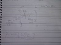
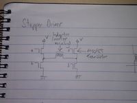
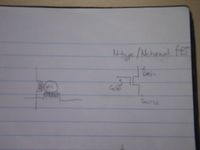
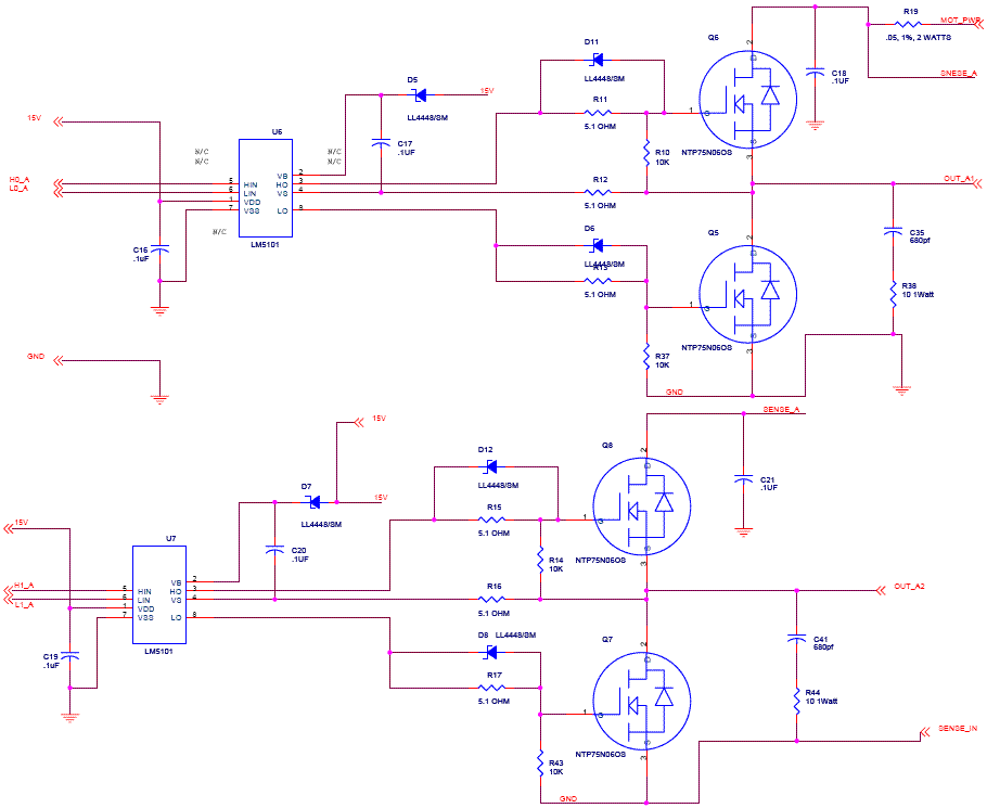
- High power robust drive circuit. N-channel power MOSFETs in an H bridge, with appropriate protection. Select MOSFETs with plenty of current and voltage headroom, and favour ones with built in clamp diodes. A stepper motor is a heavily inductive load, so it can generate voltages substantially outside the supply rails.
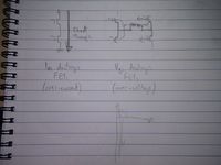
An H-bridge allows the voltage to be applied to the load (to motor winding) in either direction.
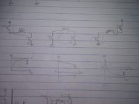
Top row: active current path. Bottom row: Corresponding Current (I) and Voltage (V) graphed against time.
From left to right: Positive applied voltage, rapidly increasing current; No voltage (except due to the resistance of the wires, gradually decreasing current; Negative applied voltage, rapidly falling current.
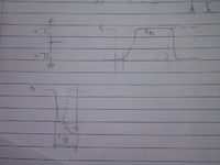
Shoot-through occurs when both transistors on one side of the H are turned on at the same time. It shorts the rails together and blows the transistors in a few us.
The overvoltage shown occurs when all the transistors are turned off simultaneously while current is flowing. Stopping the current near instantly creates a huge voltage spike. The same effect can occur if a motor lead comes loose while the driver is operating.
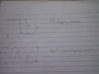
Contrast stepping with microstepping. The microstepping gives less vibration and smoother movement, and makes it possible to stop between the steps.
MOSFETS take some time to turn on and off. We need to take account of this for optimum performance (or even for to avoid the above failure modes?). See the MOSFET data sheet for exact timings.
Method of operation:
- Position instructions come to the drive from EMC. These could be step and direction pulses or some more structured data.
- The drive determines target current for each winding.
- The drive uses software PID compensation to achieve and maintain those drive currents.
- sensor: voltage induced across sense resistor by the drive current.
- actuator: PWM of applied voltage between the three normal operation modes.
- The drive determines new target current for next (micro-)step.
Prior Art
This design offers a higher power version (up to 75 amps) of a stepper motor controller, and addresses the feedback loop:
http://www.piclist.com/techref/io/stepper/hipwrbp-gm.htm
Comment by Chris Palmer
That is only part of a driver circuit. The current sense circuit is not shown and it looks like the firmware will have to do the sequencing, current control and microstepping. The LM5101 is not recommended for new designs.
There are more modern chips that you just add external FETs and sense resistors to get a complete microstepping chopper driver. For example: http://www.allegromicro.com/en/Products/Part_Numbers/3986/index.asp
References
- RepRap wiki - good references on stepper controllers - [1]
- Stepper Motor in Wikipedia
- An excellent discussion of concepts
- Control of DC motors explained - [2]
- Sample stepper motor controlled with Arduino using EasyDriver - [3]
Research
- Google: stepper motor
- Google: stepper controller integrated circuit
- Google: stepper controller chip
- Google: NEMA 34 stepper motors
Development Team
Leo.dearden - Ideas. I'm too busy to do very much at the moment, but I'll do what I can.
