CNC Torch Table 2/Control Overview
Overview
Endstops
To implement the endstops, we are modifying the GRBL file (firmware for the Arduino AVR328P) and flashing it onto the Arduino. This process requires one to understand GRBL, pinouts of Arduino, AVR chip, AVRdude uploader. GCC is used to complile c to hexadecimal.
The source code can be found at_______________ (An OSE fork on grbl github - who is making this?)
Schematic
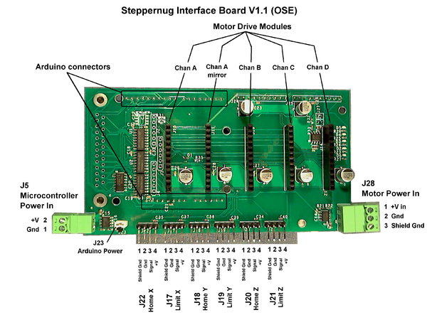
Arduino controller pin connections
Cross reference: Steppernug vs GRBL defaults (v0.7 Master, config.h)
| StepperNug Intfc V1.1 | GRBL default (ref) | |||||||
| Function | Schematic Pin |
Port | Bit | Arduino Pin |
Port | Bit | Arduino Pin |
Equiv. Function |
| Clk A | 5 | B | 5 | 13 | D | 2 | 2 | Step X |
| Dir A | 6 | B | 4 | 12 | D | 5 | 5 | Dir X |
| Clk B | 7 | B | 3 | 11 | D | 3 | 3 | Step Y |
| Dir B | 8 | B | 2 | 10 | D | 6 | 6 | Dir X |
| Clk C | 9 | B | 1 | 9 | D | 4 | 4 | Step Z |
| Dir C | 10 | B | 0 | 8 | D | 7 | 7 | Dir Z |
| Home X | 11 | D | 7 | 7 | B | 1 | 9 | Limit X |
| Home Y | 12 | D | 6 | 6 | B | 2 | 10 | Limit Y |
| Home Z | 13 | D | 5 | 5 | B | 3 | 11 | Limit Z |
| Enable | 14 | D | 4 | 4 | B | 0 | 8 | Disable |
| Spindle | 15 | D | 3 | 3 | B | 4 | 12 | Spindle enable |
| Home/Limit Interrupt |
16 | D | 2 | 2 | ||||
| B | 5 | 13 | Spindle Dir | |||||
Physical
Detail
so the interrupt works on INT0, active low. i'm not debouncing it, unless you want me to, but maybe that's not advised for end stop interrupts.
in my notes, i have that we want to use INTB (aka INT1) for spindle control. (i recall we also said something about that being an input for "home," but my notes are poor on this point; can you can explain what functionality you want here, Darren?)
anyway, by default, spindle enable is pb4, and spindle direction is pb5, which map to pins 8 & 9 respectively. but we're using those two pins for Z axis control currently. so we'd need another pin than INTB, at the least, tho i'm a fan of using the defaults personally.
regarding doing something with that INT0 interrupt, i.e. disabling the motors (and something with pin4, which would reenable them): is the idea that after an end stop is hit, the interrupt is thrown, the motors stop and G code stopped, and then the user manually moves the heads back to some home location, and then presses a button to reneable the motors? or do you want this interrupt to work as if was interpreting a particular gcode ( M2 comes to mind).
Zeroing
The x axis (long axis) has 2 stepper motors. These are typically coupled.
For zeroing, the x axis needs to decouple - so if we get the x axis out of parallel, we can jog the x axes back into parallel by hitting the end stops.


