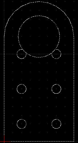
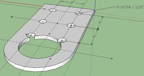
Stock Pivot Plate
Note
'Needs the Stock Pivot Plate Sketchup with 3" hole, which is the hole after the precision tubing has been welded in. Further, 6 in 60 Buildout testing has shown that the stock pivot plates need to be 1/4" shorter at the rounded part because of conflicts when 2 of these plates are put together from opposite sides in joints. To address this, please generate a stock plate where the half circle begins 1/4" further away from the rounded edge, so that the overall plate is not 16" long, but 15-3/4" long. Leave the curvature identical, just move it 1/4" inch away from edge.
Full Size Design Files, Sketchup
- 1. Realistic Design File: Needs 3" hole for exactly how 3" shaft will fit. Lengh of 15.75" as disussed above. - SKP: File:Pivplate1575-3.skp
Scale Model 3D Printing Files
- 2. Design File for 3D printing - Same as Realistic Design File except at 1/8 scale, so plate is 1" wide and ~2" long in this case. - File:Pivplatescaled-3.skp
- 3. STL File for 3D printing - same as above, exported to STL - File:Pivplatescaled-3.stl
- 4. Fixed STL File for 3D Print - see STL File Fixing for how to process an STL file to prepare it for printing - File:Pivplatescaled-3f.stl
- 5. Configuration File for 3D Print - Each type of printer uses a configuration file to accommodate differences between printers. Use this file for printing the part - File:Pivotscaled-3f-config.config
- 6. Optimized Design File for 3D Printing - For a specific printer to print a 3D print more effectively, the 3D printing file may want to be modified for faster printing. For example, the wall thickness could be changed so that the printer deposits a single-strand wall thickness for significantly increased printing speed. This will have to be determined by printing the file from points 6-7 and seeing the results. Wall thickness must be balanced with structural integrity/printability of the resulting parts. Further, sacrificial bridges between parts may need to be added so that tall structures being printed do not shake around on the moving printing bed.
- 7. Optimized STL File for 3D Printing - File:Pivplatescaled-3-opt.stl
- 8. Optimized Fixed STL File for 3D Printing - File:Pivplatescaled-3f-opt.stl
- 9. Configuration file for Optimized 3D Printing - File:Pivplatescaled-3f-config-opt.stl
Laser Cutting
For Laser Cutting out of stiff construction paper at 1/8 scale - we need to start with a scale model in Sketchup, corresponding to Design File for 3D Printing. Take the component to be printed. In order to generate a flat structure, the DXF can be generated directly from this SKP file.
- 10. Laser Cutting File - DXF generated from SKP Design File for 3D Printing: File:Pivplatescaled-3-laser.dxf
For non-flat files - such as tubing - this requires more work. Start with the tubing file in sketchup, export to DXF for the one side - and basically draw the rest of the tube as a flat structure - so a rectangle with perforations for the 4 folds that will allow a flat cutout to be folded into a 4-sided tube. Once folded, the tube should be taped together, or a tab should be added so taping together is easy.
Full Size Files for CNC Cutting (Acetylene Torch, Laser, Plasma)
- 11. SKP Design File for Generating CNC Torch/Plasma Cutting Files: Same as above except the hole accommodates a piece of precision tubing with 0.5" wall - so it is 4-3/16" diameter to allow 3/32" welding gap. This kind of spacing has been tested with laser cut metal. - File:Pivplate1575-4.skp
- 12. DXF CNC Cutting File - same as above, but exported to DXF. - File:Pivplate1575-4.dxf
Older Version
DXF file - File:Stockpivot.dxf
Note: the correct large hole diameter in the above is 4.75", which gives 1/8" room around the DOM for effective welding.
Note: the above is used to generate a CAM file for CNC Torch Table cutting and Laser Cutter modeling - for the pivot plate. In practice, a 4.5" OD DOM with 3" ID is welded inside the 4.75"-4.875" hole (Mickey Mouse hole) to generate a pivot plate for a 3" shaft. To generate a CAM file for 3D printing, one must consider the 3" tubing and print out a 3" hole, not a 4.75"-4.875" hole. 4.75" is recommended as a hole for CNC cutting (leaves exactly 1/8" space around DOM for welding) - and a 4.875" hole is recommended for manual cutting to address inaccuracies.
- File:Stock Pivot Plate.skp
- File:Stock Bonding Plate 8 inches x 16 inches.skp
- File:Stock Spacer Plate 8 inches x 8 inches.skp
Links
- Samthetechie Log
- Print how-to - Ultimaker Post on Using Sketchup for 3D Printing.

