CNC Torch Table Z Height Control

Automatic capacitive sensing version of CNC Torch Table Height Controller
This is the automatic height levelling version based on the new TorchHeightCTRL_V.02 pcb. (All Sources on GitHub: [[1]])
Design rationale
The new pcb is an all-in-one board, that adds some peripheral interfaces to the appication, like for endstop or a future direct user interface (Display).
In the automated version the 0mm-distance / start-position should be found automatically by homing. From this it will take a sample and then goes to 30mm height and take another sample for calibration. Then it will go into a loop and trying to balance the distance around a pre-set default-value of 15mm. But if you then push the button of the jogwheel you switch from autobalancing- into manual-mode and change this 15mm-default-value by turning the jogwheel. Pushing again switches back into autobalancing mode.
BOM
| Quantity | Part | Supplier |
|---|---|---|
| 1 | Arduino Nano V3 with USB-cable | [2] |
| 1 | TB6600 stepper driver | [3] |
| 1 | KY-040 Rotary Encoder | [4] |
| 1 | Knob for rotary encoder (must be 3d-printed on your own !!!) | [5] |
| 1 | Power-Supply | [6] |
| 1 | Stepper Motor 17HS19-2004S, Nema17, with 2A and 59Ncm holding torque | [7] |
| 1 | Mechanical EndStop | [8] |
| 1 | Sensor-probe | to be selfmade, from a thick piece of copper wire and a BNC-cable (but a commercial version also exists) |
| 1 | 5-pole DuPont connector breadbord-ribbon-cable, female2male | [9] |
| 1 | 1-pole DuPont connector breadbord-ribbon-cable, female2female | [10] |
| 1 | D3D universal axis, as testrig or torch-mount | [11] |
| 1 | TorchHeightCTRL_V.02 pcb | can be ordered from Aisler as readymade project [12] (but you have to register there to see the project) |
| Set | Set of electronic parts for soldering on the pcb | can be ordered from Mouser as readymade project and can be accessed at [13] (there you have to type in as project-key 64fff8ecbf) |
Wiring Schema
Warning: The phoenix-contact powersupply connector has NOT the same configuration than the connector of the same type on RAMPS-boards !!!
Dont use the plug of a powersupply that was previously configured for use with a RAMPS-board and has 2 x 12V. The TorchHeightCTRL_V02 board has 1 x 5V and 1 x 12V and will be blown immedately if you give 12V to the 5V line !!!

Firmware
Arduino-Code on Github:[[14]]
Manual adjustable version of CNC Torch Table Height Controller
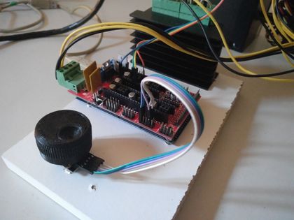
This is a simple POC-version that allows a manual adjustment of the Z height by turning a jog wheel (see demonstration video on youtube: [15]). The wheel can be 3d-printed [16] and is connected to a rotary encoder of type KY-040.
- manually steered height control
TB6600, Arduino_Mega/Ramps, KY-040 rotary encoder
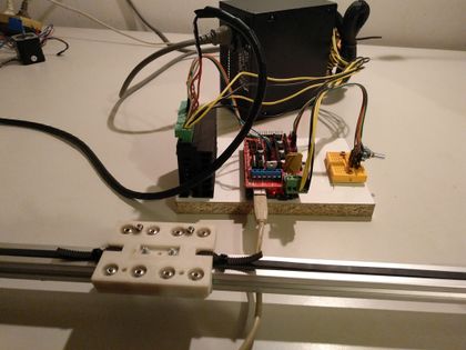
stepper driven lineardrive


- demonstration video on youtube: [17]
Design Rationale
With this rig it should be possible to manually operate the torch table height by following its slowly moving and regulate the height personally. This can be useful even if in the full version there is a capacitive sensor doing automatically that task, but one may use it then for setting the starting height or use it in other applications where a frequent manual control is an appreciated option.
The rotary encoder gives up to 20 pulses per revolution to an Arduino-Mega, which translates it into a number of motor steps and triggers these by a TB6600-based stepper-driver. A RAMPS 1.4 may act as a connection layer on top of the Arduino, but can also be omitted. We will show here which pins to wire on the Arduino and on the Ramps as well.
The firmware consist only of a few lines of Arduino-code, which makes it easy to extend and modify.
BOM
| Quantity | Part | Supplier |
|---|---|---|
| 1 | Arduino Mega 2560 | [18] or under Linux the CHG340-version: [19] |
| 1 | Ramps 1.4 | [20] |
| 1 | TB6600 stepper driver | [21] |
| 1 | KY-040 Rotary Encoder | [22] |
| 1 | Power-Supply | [23] |
| 1 | Stepper Motor 17HS19-2004S, Nema17, with 2A and 59Ncm holding torque | [24] |
| 1 | 5-pole DuPont connector breadbord-ribbon-cable, male2male | [25] |
| 1 | 5-pole DuPont connector breadbord-ribbon-cable, female2female | [26] |
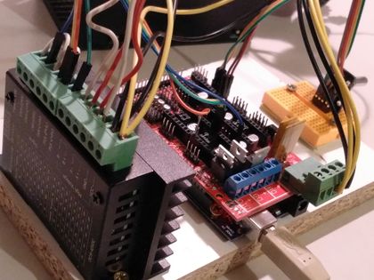
Wiring
There are 3 kind of connections:
- Power-supply to Ramps/Arduino
- Rotary Encoder to Ramps/Arduino
- TB6600 to Ramps/Arduino
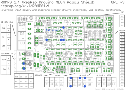
Ramps-pins to connect are marked with a blue point
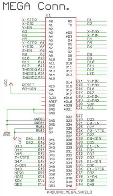
Mapping of the Ramps-Pins onto the Arduino-Mega ports


Power-supply to Ramps/Arduino
1. Ramps: Connect a 12V/5A-Line to the MSTBA4-Port an the Ramps, by using a phoenix-contact plug. This will provide power for Motor as well as board-power for the Arduino-Mega.
2. Arduino standalone: The Arduino musst be supplied with 5V to 12V. This can be done by the USB-connection to a desktop-pc or by a standard wall-wart ac/dc-adaptor (5V, 2A) for the Mega.
RotaryEncoder to Ramps/Arduino
The KY-040 RotaryEncoder has 5 Lines: GND, +5V, SW, DT, CLK. Connect these either to the AUX2 port of the Ramps, or directly to the corresponding digital I/O ports on the Arduino-Mega.
GND --> GND
5V --> 5V
SW --> D44
DT --> D42
CLK --> D40
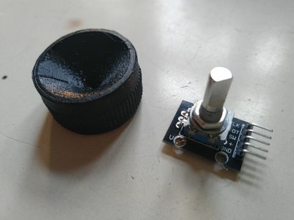
KY-040 RotaryEncoder with 3d-printed jog-wheel
The pins at the AUX2 port are conected to the rotary encoder


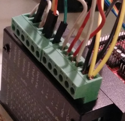
TB6600 to Ramps/Arduino, Motor and Power
The TB6600 stepepr driverhas three phoenix contact like connectors,
- one 6-pin to the Ramps
- one 4-pin to the motor
- one 2 pin to power-supply
The 6-pin connector has the lines ENA-, ENA+, DIR-, DIR+, PUL-, PUL+.
Make a bridge between ENA- and DIR-, together with a second bridge from DIR- to PUL-. The PUL- contains a second cable which goes towards GND on the Ramps Extruder E0 port. So in total there are 4 wires going either to the Ramps or directly to the Arduino-Mega:
1. Ramps:
ENA+ --> EN
DIR+ --> DIR
PUL+ --> STEP
PUL- --> GND
2. Arduino-Mega:
ENA+ --> D24
DIR+ --> D28
PUL+ --> D26
PUL- --> GND
upper left corner: 2 white cables make a bridge between ENA-, PUL- DIR-. The PUL- contains an additional cable (orange) that connects to GND on the Extruder E0 port of the Ramps/Arduino
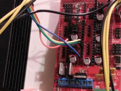
The pins at the extruder E0 port are connected to the TB6600


The 4-pin connector has the lines A+, A-, B+, B-.
In the case of a bipolar stepper motor with 4 wires two of them are the ends of one coil. Connect them like this:

An example for a tested Nema17-stepper with 2A and 59Ncm holding torque is the 17HS19-2004S, see [27], [28].
The 2-pin connector has the lines 12V+, 12V-.
Connect these to a power-supply which can deliver at least 5A. The TB6600 stepper driver is rated for up to 4A and 9-36V DC. That means you can instead of 12V also connect 24V or more towards it.
Firmware
Arduino-Code on Github: [29]