Aidan Williamson Log 2014
Old Logs:
Links:
- DIY TAZ BOM
- My YouTube Channel
- Water Wheel Transplanter on Farm Hack
- CEB Press 6 code
November 2014
11/7
September 2014
9/5
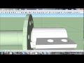
Work I've done for the design of a CNC Plasma Table for a local welder
- Project Overview
- Bill Of Materials and Cuts List
- Addendum 1
- File:BFCNC5x10.skp
- File:BFCNCSchedule.pdf
August 2014
8/24
All of my emails with Tom about the power cube v7 se: File:Aidan Tom PCv7SE Emails.pdf
8/23
http://img.youtube.com/vi/K75vRkw_GLY/default.jpg
8/22
http://img.youtube.com/vi/K9uUl97X0KQ/default.jpg
8/21
Started to remake pump and engine plates for Structural Power Cube. Not much progress made as we ran out of gas and I had to run to sweiger. Slow day all around.
8/20
File:Modified9inchWheelHub.dxf
PC v7 SE build. Engine plate needed to be remade. Several other issues here and there. Slow work figuring out the geometry. Pictures tomorrow.
Made a heat diffuser for the stove.
8/19
Structural Power Cube Build. Taking longer than expected - as expected.
http://img.youtube.com/vi/ZeuBlPsT2Js/default.jpg
8/18
Microhouse Module Integration with the group in the morning. Marcin's Cake. Power Cube v7 Structural Edition preliminary assembly for documentation. We will build one slowly and take pictures and then have some n00bz build one with the documentation we create.
8/17
Drew new version of 3 inch wheel hub
http://img.youtube.com/vi/A1iurhtI1GQ/default.jpg
8/12 - 8/15
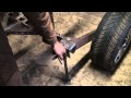
LT4 snapped rear left axle right before the thrust bearing. Showed Will how to use the bridgeport to machine the keyway and bolt hole to make a new one. The plan is to switch to 3" axles with a keyed clamp instead of bolt-through-flange for wheel mount.
Cleanup of uHouse site.
Video for Fred & Scott Eisele for hydraulic modeling of CEB press:
http://img.youtube.com/vi/9KY8goLaG7A/default.jpg
8/11
Moved the shop press to the site for compressive testing of bricks. First one I tested was like butter. Moved mortar to the site. Moved window modules to the site and taught Churchill to operate the LT4. He has earned his PhD in LifeTrac operations.
8/10
Replaced 5/16" Motor mount bolts on the structural powercube (v7) with some welded plates because I didn't have time. Put that on the back of LT6 which has two bad power cubes on it. Got LT6 out of the uHouse site and brought the bad PowerCube to the shop.
8/9
LT4 cracked a drive hub in the same wheel module Churchill and I fixed on 8/7. We had not installed the hub deep enough in the motor's tapered shaft causing some play which ended up with the key ripping up the motor and cracking the hub. About 4-5 hrs to fix.
8/8
Pulverizer for 6 hours, brick pressing for 5 hours. LT4 left chain popped off due to inadequate tire pressure. About 1hr to fix.
8/7
LT4 left front wheel module repair. Sprocket on the shaft side of the double chain coupler was ripped up.
8/6
Brick pressing
8/5
rain
8/4
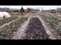
First day of pressing bricks. Today's workflow: garden rototiller going over pre-pulverized dirt with cement shoveled into buckets carried to brick press, pressed, and then brought to nearby pallets. 1 powercube because we don't have time to tinker blindly anymore.
Tomorrow we will use the hopper loaded by a lifeTrac if it doesn't rain tonight.
File:WKJCEB.ino added 5 second shaker turn on upon button press to automode. untested
8/3
day off
8/2
CEB press blew a fitting or an O-ring in the morning on 2 power cubes prompting work on 2 power cube mode to halt while Marcin investigates the hydraulic circuit. There is something funky going on with the manifold and the various pressures throughout the system. Needs attention from someone who knows what's going on with that stuff. Hopefully a hydraulic circuit diagram will materialize from Marcin's direction.
Stayed up till 5am with team velocar to try to machine some of the components at 4am my legs stopped working and I laid on the floor throwing chunks of apple at a birds nest after Yann told me that the 6mm holes I drlled were supposed to be tapped 6mm (drawing's fault).
8/1
Foundation work at microhouse foundation work.
Set up TIG welder for velocar project.
Cleaned workshop
July 2014
7/31
Added bushing stops to the CEB press drawer so that they wouldn't push out anymore. Further testing of CEB press with 2 power cubes. The drawer is the problem area.
- The flow rate is too high for the 2.5" cylinder so we turn on the shaker anytime the drawer moves.
- The pressure when the drawer is retracting is ~2100PSI which means that any pressure transient will cause the pressure sensor (triggered at 2300psi) to go high so the automode and test routines are interrupted.
- There is a mechanical problem where the drawer clips the top/bottom of the chamber it slides through. This is the high pressure transient I was mainly referring to in the last bullet
7/26 to 7/30
- Set up Chinese CNC Router for the velocar project
- MicroHouse help
- Adapting CEB press to 2 powercube mode
- Adjusting code to comply with emergent specifications
- Built a soccer field (weekend)
7/25
Brought new arrival Will up to speed on the capacitive height sensor project. He already found a problem where my Wire.endTransmission(); calls were not properly set up with a stop argument for terminating the i2c bus connection. He is now playing with that project as I return to Ceb Press auto code to implement some design requirements.
7/24
Got the subpump working and drained the water from the septic tank hole at the microhouse site
7/23
First thing helped Jim diagnose the PowerCube v7 on the LifeTrac v4. We noticed that no fuel was leaving the fuel pump. We felt vacuum pressure on the hose leading from the cylinder that powers the pump so we thought maybe it was bad. We took it off and put it on the structural powercube v7 and let it run for about 20 minutes. So the pump was fine. We put the pump we took off the structural power cube and put it on the lifetrac one and it started up fine. So it's a mystery but Jim has a few theories.
While the test brick team was getting soil ready and clearing out the old workshop, Gabriel and I started testing the auto code. We found a few things:
- The pin F0 that reads the high pressure sensor was bad. We traced it all the way back to the chip and saw that the chip was not outputting 5v when it should. So we soldered a jumper between pin f5 and f0 and changed the pressure sensor to pin f5
- We had inverted logic on the Pressure_Sensor which meant we were reading high pressure when it should have been low
- It is best to throw a serial print of pressuresens in the void loop when calibrating the pressure sensor. It is also good practice to manually jerk the machine around in manual mode to make sure that it only reads high pressure when the cylinders are at extremes of motion
- We had been using an int and a long when doing comparisons with millis() which caused issues with the obstruct passage and load soil (or whatever it's called) states. in a signed long, the MSB is the sign bit. Credit to Gabriel's nimble intellect on picking that up when we were reading a -1 for elapsed time in the state machine.
- The structural power cube was squiring oil out of the swivel fitting at the pump output every time we hit high pressure. I tightened it with a crescent wrench but it ought to be tightened more.
- There is a chance (untested) that the stop positions that are set in test mode are not what happen in automode.
Automode has successfully pressed a brick
7/22
Welded bolt tabs for bucket -> lifetracs IV and VI quick attach. Took the LifeTrac to the microhouse site to do some excavating. I had some problems with the powercubes stalling out which I attribute to a combination of any of these factors:
- The gas in the cubes was stale - drained from a power cube that was sitting for over a year.
- I was driving the air cooled engines in the sun at around 95F
- I did not have the experience maneuver the tractor without stalling during digging or bringing a load up hills
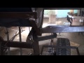
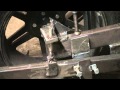
I noticed the newer power cube was cutting out more than the bottom one so I figured it wasn't running with enough throttle. I set up a foot-operated lever that would pull on the hole on the throttle reistrictor in this picture:
I was revving the engine as I would go up a slope with a bucket of dirt. This may have been detrimental to the engine because it will not start now. I am not reading a significant voltage between the two wires that connect to the fuel solenoid when the ignition is switched to "on".
Helped Gabriel fix a problem with the CEB Code where you couldn't exit auto mode. It now exits correctly. There was a digital write logic level issue in switchAuto. We set up the CEB press for test pressing and found that there were issues with the second ceb press controller. We hooked the new controller to the old ceb press and found that the drawer would bounce before reaching anywhere near its full extension. From this I deduced that there was a problem with the pressure sensor activating prematurely (at low pressure). We need to do more testing on it. I will try:
- installing a pressure gauge on the hydraulic line
- serial printing when high pressure is read
- attaching a momentary switch in parallel with/replacing the pressure sensor
It was quite hot and we were tired so we called it a day a bit early
7/21
Definitively connected the hydraulic tanks together on the lifetrac iv. The problem from the night before where turning off the top cube would cause hydraulic oil flow out of the breather valve on top was solved by adding another breather valve on the side of the top tank with an elbow pushing it up about 8".
7/20
Cut off the old rusted-out back leaf spring hanger at the rear right wheel and replaced the shackle. The leaf spring is no longer flying through the bed of the truck.
7/19
Changed the oil and oil filter on the truck with Jim. I need to upload pictures to the Farm Truck Oil Change page.
7/17
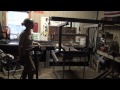
Helped Jim set up a power cube repair station.
Augmented the CEB Press VI Controller Emulator with a new button and LEDs
Set Jose, Gabriel, and Victor up with a workspace to do some serious documentation brainstoring.
7/16
CEB Press code
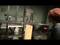
Debugged the malfunctioning CEB press controller. The down button was not working:
- Tested the switch
- Looked over all solder joints on back. Reflowed questionable ones (questioned liberally) and cleaned spatter off in many places.
- Measured voltage at pin b5 which is the output for the mosfet for the solenoid. it read 1.5v when on
- Disconnected the bias resistor from the output to the mosfet and measured the voltage at pin b5 again. 5v
- Attempted to measure the resistance of the bias resistor and in doing so accidentily shorted the resistor to its desoldered mount hole. The LED illuminated.
So it was a problem with the solder joint at that spot where I just so happened to be measuring.
Here is the culprit after being reattached:

7/15
CEB Press Build
Fixed power cube 7. The throttle lever cable was not installed correctly so the choke was never engaging. Spraying ether into the air intake showed that the other systems were working. Many thanks to Wayne Toffelson of TNT Small Engine Repair in Savannah, MO for walking me through that process.
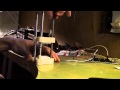
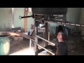
Oscilloscope arrived for the cap dac project but I have not yet started to use it because the CEB press controller code has well eclipsed it. CEB Press 6 Control Code GitHub Repository. This is mostly Gabriel's work but I have made significant contributions so I believe I can call myself a co-author. Here is a picture of the test jig I made for testing the code:

7/14
CEB Press
7/13
Working on implementing some test routines in the kliment CEB press code. Here is a gif of the timing sequence of the ceb press for reference:

7/11
Afternoon:
Cap Sensor is now reading data. Random value in CAPDAC while I figure that out so it stays around 1pf but varies in the fF range. Here is some data from random movement of the cap sense jig. File:CAP SENSE DATA 7-11-2014.txt
Morning:
File:Cap Sensor Email Chain 7-11-2014.pdf This is all of my emails to Paul Neelands regarding the ad7747 board he designed. It will be useful for anyone who wants to be brought up to speed with this project.
Capacitance Sensor Code as of 8:12 7/11/2014
The program seems to be executing properly. If you add a Serial.println command after the while loop in the void loop then it shows that the program does leave the while loop and there is no dead-end anywhere.
At this point I think there are two possibilities:
- There is parasitic capacitance of a higher order than the sense line.
- The Chip has suffered from over-prototyping and needs to be retired.
7/10
Fiddled with my code for the height sensor in the morning but didn't really make any headway. Fixed the broken welders with Victor and Guillame. All 6 Millermatics are now provisionally operational. Got some dirt from the microhouse production site with lifetrac 6 and dropped it off by the old CEB press. Finished welding the patches on the slurry mixer and installed the drain pipe. Showed Yann how to use the oxy-fuel torch.
7/9
Sketchup:http://img.youtube.com/vi/hEUz68Y5aFM/default.jpg Real Life:http://img.youtube.com/vi/NZqa3A80I5Q/default.jpg
File:Capacitance Test Jig.stl
Capacitive Sensor Code 7/9/2014. This is printing serial data every second or so. The problem is that the data does not change. Sits right at 8.192pf no matter where my plates are. So there is something going wrong. I am confident that I have initialized all my registers properly. There must be a problem with the wiring or the way I am reading the data. The plates measure 2.45 V relative to each other. The shield lines are virtually driven to the same potential as the sense line (30mv maximum difference measured with Chinese DMM). I will wait for a scope to debug further. Perhaps i'll play with the i2c reading in the meantime. Saelig sold us a scope that was out of stock and failed to inform us for 4 days. I had to call them to figure it out and they didn't even offer to upgrade my shipping when I switched to a more expensive one. I left scathing reviews around...

7/8
Bought a winch at Menards and pulled the bobcat out of the mud with it. Took pretty much all day. hard work. Welded patches on large steel drum with Devin
7/7
Milled some parallel plate capacitors to 30mm x 30mm out of 6061 stock. In order to mill on the bridgeport I had to cut threads in the drawbar because it would not pull the collet all the way into the taper. I used a 7/16th 20 tpi die. In order to successfully do this I had to redrill, tap, and make a setscrew (1" 1/4 - 20 bolt with a weld bead on the end) for the die wrench. This is exemplative of the obstacles that might pop up when you try to do something seemingly simple here.
7/6
PowerCube Workshop.
7/5
Worked all day on the cap height sensor. It now reads data. I need to do testing with it. Working with Paul via email on that. Current code can be found here: Cap Height Sensor Firmware 7/5/2014
7/4
Power Cube Documentation: Hydraulic Reservoir Module in the morning with Michael
Power Cube Workshop: Found a suitable induction motor with Tom. Attempted to machine pulley for uPowerCube with Yann. The mini lathe is not a quality machine. The first attempt yielded poor results due to clunky collaboration between Yann and me - mostly due to the inability to communicate well during the noise of the PowerCube workshop. The first pulley will either be fixed or a new one will be machined properly.
Conducted MudHut Hunnies Orchestra
7/3
Worked in the morning on the capacitive sensor. Wrote the code for it which can be found here: pastebin. It's not working. Currently talking to Paul on why that might be. Need time to wrap my head around it.
In the afternoon I cleaned out Tristan's old room for use as an electronics bench so that I may find some environmental tranquility while I think about this sensor.
Tom_Griffing arrived with some power cubes. One is a micro cube which is driven by an induction motor. The drive pulley on it was machined without proper tools so we drilled a hole in a new one. This took a considerable amount of time - as all things do. At one point I thought I had to make a chuck wrench for the mini-lathe in order to mount the pulley. While searching for a drill chuck wrench to mount the stock for the mini lathe chuck wrench I found the chuck wrench for the mini lathe. Irony. Anyway, after that we spent about 2 hrs dancing around the mills and lathe in order to do something that should take 30 mins. It was a good time, though.
After that I had Devin help me gear the lathe in order to spool faster. Video should arrive soon. I ran into a problem with my tensioner where the wire would grab the tensioner and pull the entire table that the idler is mounted on. Very disconcerting when you are standing between the lathe and the table. I need to brace the table and make it safer and then we are in business with this welding wire recovery.
7/2
Showed the group how to use the LifeTrac 4. It went well but slow with only 1 powercube. The battery was dead and then the solenoid wasn't working (bypassed it with a fat wire) so it ended up taking a bit longer than expected.
Finished the coil spooler and started spooling. We need to gear the lathe (desperately) because I'm only getting 120RPM (i estimate) and at that rate it will take me over 6 hours to finish all the spools (it was a simple fermi problem). That ain't happening. So it's either we find a new drive mechanism other than the lathe or we gear the lathe to spool this rusty weldin' wire.
7/1
In the afternoon:
Installed broken tractor chain on LT6, got new arrival Michael into some grinding and welding, started working on a simple coil re-winder which then turned into showing Guiamme (sic.), Emily, and Victor how to use the oxy-acetylene torch. Remembered how one thing can turn into a million other things very quickly here.
In the morning:
Relevant Links for AD7747
3d printable clamp for attaching cap sensor ring to torch:
File:Cap ring clamp.skp
File:Cap ring clamp.stl
http://img.youtube.com/vi/9v0jF8Fyp3w/default.jpg

June 2014
6/30
Arrived at fef. Worked with Gabriel on soldering the capacitive height sensor module. The pcb was already tinned so it was just a matter of hot air and some touch-ups with the soldering iron.

With gabriel, created a very simple version of the capacitive ring found on Sensing Distance from Work Piece. Just a piece of steel from a 5 gallon bucket handle formed around a 1.25" socket and flattened in a vice. Will experiment with it tomorrow to see what kind of readings it gives. Pictures forthcoming.
Later on, cleaned the area around the torch table and started thinking about how the sensor will interface with the current electronics. Will test the cap. ring with a spare arduino just for testing. Started refreshing my memory of i2c with this tutorial: i2c tutorial part 1/7
May 2014
5/21
Note: open digikey carts one at a time or they might get combined
Ordered Parts For Fab Modules Stepper Motor Drivers (4 count)
Ordered Parts for Fab Modules Stepper Controller
I also ordered some copper clad PCB here: ebay I also had to have the board layouts printed with a laser printer on glossy paper at my local print shop. They charged me $8.50 which I feel is a bit expensive.
Total Cost (w/out shipping or tax) : $93.05
5/17
Ready to begin with the Fab Modules Triple Stepper method for controlling the TAZ for milling. I imagine the RAMBO and the triple stepper boards next to each other with a large jackknife switch to change between the two. Things i've noticed so far:
- The A3982 Stepper Driver is a SOIC only package.
- You will need to make two drivers which recieve the signal from the stepper controller
- It's about $80 in parts to purchase everything for this upgrade.
March 2014
3/17
Install Fab Modules in Ubuntu 12.04 courtesy of mkeeter.
3/6
I emailed John. These were my questions:
1) In the BOM it lists the parts for a stepper driver. Is it possible to use the RAMBO stepper drivers or do I need to
   create an entirely new driver board for milling use?
2) What software do you recommend using? I found the MTM Fab Modules software but have yet to experiment with it.
His Response:
my preferred way is to create an entirely new driver board for milling use that goes with the MTM Fab Modules software.
http://kokompe.cba.mit.edu/index.html
http://mtm.cba.mit.edu/fabinabox/dev/triplestepper/overview.html
I'm awaiting further clarification in order to proceed in automating the toolpath.
3/1
Looks like I was using the 24V motor from the BOM at 12v from my PSU. I will need to buy the right motor or use a dc-dc converter to get the 24v i need.
February 2014
2/28
Hydrafabber CNC Spindle has been installed on the TAZ. Some media is below.

Hydrafabber Pics
http://img.youtube.com/vi/rJMkfLgo-N0/default.jpg http://img.youtube.com/vi/z9Z09NNhhtI/default.jpghttp://img.youtube.com/vi/VfQxZMqks_A/default.jpghttp://img.youtube.com/vi/stR6FzeeTsc/default.jpg
2/18
2/15
Working on a Product Development Cycle for Small Scale Farmers based on a thesis by Sam Shepherd, MEE and a collaboration with James Tangorra.
2/8
Printed CNC Spindle Mount:
http://img.youtube.com/vi/2kKC2A5IXlM/default.jpg
2/5
If you are going to use a 12x12 inch bed on the Taz then you will need these bed corners
2/4
Had a snow day on Monday so Gabi and I were able to model most of the water wheel transplanter in sketchup. Automatically updating sketchup file found here
January 2014
1/21
In the wake of two days of failed prints, an update on the Taz:

PLA & The Budaschnozzle:
- Do not let the Budaschnozzle idle at temperature unnecessarily
- Make sure the extruder and the hot end are perfectly alligned
- Slide filament through both holes as you bolt them in. The filament should move without much resistance.
- Install a fan pointed at the heatsinks but blocked from the heater block
I learned those things the hard way yesterday.
Bed adhesion
On my first print a glass bed at 70C was used with no problems. My second print would not stick until I used an elmers glue slurry. 4 Parts water to 1 part glue painted on when the bed is warm.
1/11
The last week was basically spent rethinking our decision on 1/3 to use 3 smaller barrels and designing a way to use 2 55gal barrels.
This required cutting of the old saddle and building/mounting a new, much larger, heavier one. I have my doubts but am otimistic. I want to see some testing with the 1000lb payload on there. Gabi is almost finished the waterwheel lift mechanism. There is no video update because of technical difficulties.
Here is a video of my first print on my Taz!
http://img.youtube.com/vi/MW8Qi5iNOOc/default.jpg
CONGRATS - EPIC WORK on TAZ!!! -MJ
thanks!
1/8
Nice coverage in The New Yorker.
Completed my first print. Video is rendering at home. I will upload it another day. For now I have a video of stopping a leak in the Budaschnozzle.
http://img.youtube.com/vi/W7acDWe4hqU/default.jpg
We decided to use two 55gal drums. I cut off the saddle and will begin workign on the new one on Friday.
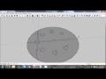
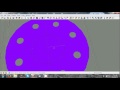
We are making three 25" wheels from laser cut 11ga mild steel. Here are the files we sent to the machine shop:

File:Water Wheel 25.dxf
File:Water Wheel 25.skp
1/6
A fun way to navigate this wiki is to use the random page tool. You can put this link: http://opensourceecology.org/wiki/Special:Random in your bookmarks toolbar if you are in mozilla.
This is from the other day:
http://img.youtube.com/vi/G4G7GXfV9ns/default.jpg
I started to look at the budaschnozzle. It needs to be cleaned. I started that process but ran out of time. I will document it with a video when I finish.
1/3
We decided to add 3 15 gallon barrels to the sides of the 55 gal barrel to give a total capacity of 100gal. We also lengthened our shelves. I'm ready for a day off, which is coming.
http://img.youtube.com/vi/Gpx4PmBSZtg/default.jpg http://img.youtube.com/vi/dfrwYHx87ec/default.jpg
1/2
So Christmas happened and then other stuff and it's now apparently 2014 and I haven't finished the Taz or the Water Wheel...
Ordered a part for the nozzle and then it should be 100% operational after a cleaning. Haven't had any time at all to work on it other than to build a more permanent space for it in my room.
The water wheel is coming along. I will post some videos from youtube below. It is now day 9 but they haven't really been full work days. Nothing like a production run at FeF as we are using rusty material which is not square and we don't have a complete design going in to it. It does look pretty good, though.
Finished
- Main Frame
- Wheels
- Barrel Mount
- Seat arms
- Seats
To Do:
- Water Wheel Welds
- Lots of Grinding
- Plumbing
- Water Wheel Axle
- Water Wheel Lift Mechanism
We are also considering adding another barrel for 2x water capacity.
http://img.youtube.com/vi/pcfBlHZqhGI/default.jpg http://img.youtube.com/vi/2liSUr8ZTw8/default.jpg http://img.youtube.com/vi/yOSPMLqozg8/default.jpg
http://img.youtube.com/vi/Colu1FynxQU/default.jpg http://img.youtube.com/vi/cS_mOMHhFD0/default.jpg http://img.youtube.com/vi/Y1YyX753Sfg/default.jpg http://img.youtube.com/vi/TTfgEkePOZU/default.jpg