April 2011 Production Run BOM
Jump to navigation
Jump to search
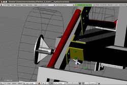
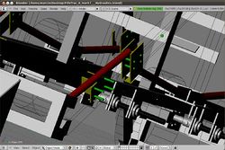
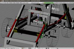
Download open source tractor 3D source code
Cut List: Tractor
Square tube: 90.3' total
- [4] 76"×4"×4" tubes for base (shortened by 16")
- [3] 5'×4"×4" under base tubes.
- [2] 52"×4"×4" vertical chassis centre tubes.
- [2] 55"×4"×4" vertical chassis tubes for front corners.
- [2] 59"×4"×4" vertical chassis tubes for rear corners (PC mounting area).
- [2] 68"×4"×4" top chassis tubes.
- [3] 44"×4"×4" top chassis tubes.
Rounds:
- [4] 28" × 1-7/8" axle shafts (22" before; turn gussets around for easy wheel takeoff)
- [1] 56"×1-7/8" loader mounting shaft.
Sleeves:
- [4] 8” sections for shaft – loose for wheels
Rectangle:
- [2] 100"6"×3" 3/8" tubes for front loader arms.
- [1] 45” more for cross support
- [4] 6"×4" 1/2" angle-iron to attach re-enforcing tunes to Loader arms.
- [4] 4-1/2" 1-7/8" DOM to mount shafts through the frame.
- [4] 3-1/2" 1-7/8" DOM to mount loader shafts to loader arms.
- [8] thrust bearings - in the form of large washers with 1-7/8" hole to go between frame-shaft-DOM-mounts and loader arm mounts.
- [4] 6" bushings/DOM to weld in gussets and wheel mounts.
Plate:
- [12] 10"×8"×0.5" steel plates to mount flange bearings and hydraulic motors to frame.
- [4] 6"×8"×1/2" QA-plate to mount motors to QA-motor plate.
- [2] 6"×12"×1/2" plate to mount H-cylinders to frame base.
- [4] 6"×4"×1/2" plate to weld to H-cylinder base plates.
- [12] 1" diameter-hole nuts to weld into above plates.
- [1] 1/4"x4×36" plate to mount Valves to.
- [4] 5"×12"×1/2" plate to connect Front H-cylinders to loader-arms.
- [4] 10×10×1/2" plates to make wheel mounts.
- [8] 4"×4"×1/2" plate cut diagonally to make [16] gussets.
- [16] thrust bearings - in the form of large washers with 1-7/8" hole - torch these on torch table from 1/8" stock
- [4] 1”x3”x6” slabs for loader eyes
Steel Tracks (for Wheels)
- Chain - 70 feet - $270 at $3.37/foot
- Links - $28
- Rebar - 140' at $1.57/foot - $220 – minus 12-16 bars
Power Cube & Seat mounting metal:
- [4] 36" 4×4" 1/4" thick angle Iron
- [1] 88" 2×2" 1/4" angle iron
- [1] 192"×4"x3/8" plate
Cut List: Power Cube III
1/4"x4"x8" mild steel square tubing - 22 feet @$8.15/foot - $180 - 286 lb 1/4"x4"x4" angle verticals – 2 of them 20” tall
- 27x29 base
- Pump mount plate - 1/4"x6"x8"
- Engine mounting - angle
- Pump mounting plate
- Eyes
- Fingers -
Cut List: Pulverizer
- [3] plates 1/2"x8"x12", shaft mounting
- [12] tines sleeves 3” long - tube to fit 1-7/8" shaft
- [48] tine blades, 3/16"x2"x5”long
- [1] 1/4"x2"x4" is 56" long
- [2] arms 1/4"x2"x2" square tube, 2'
- [2] arm sleeve, 3/16"x2.5"x12”
- [2] depth sleeve, 3/16"x2.5"x6”
- shaft, 1-7/8"x54” long
- [2] height adjust 15”
- sheet 4'x33”
- [2] sleeve attach 4x6x1/2
- 1/2"x4"x22" cut into 4,10-12 right trapezoid
- 1/2"x3"x48" finger
- [2] 1/4"x2'x4' bucket metal
- 1/4"x2'x2' square for 2 sides
- 38” rostrum, ¼"x2"x2" tube
- 3/16"x2.5"x6” rostrum sleeve
Cut List: Quick Attach Plates
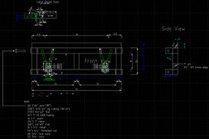
(See Open Pario for design)
- [6]1"x5" pins (30")
- [129"] 3/16"x3" sq tubing
- [113"] 1/2"x3" flat
- [6"] 1" DOM tubing
- [24"] 1" rebar
- [66"] 1/4"x2" flat
- [6"] 1/2" rebar
- [15"] 3/4" threaded rod
- [8] 3/4" lock nuts
- [2] 3/4" nuts
Cut List: The Liberator
U-Channel Frame- 7/16" thick heavy u-channel, 6" wide
- - Dalton Hydraulics cylinders and solenoid valve
- [2] 42" - verticals
- [2] 29" - table holders
- [4] 21" - bottoms and tops
- [2] 10” - chamber spacers
- [2] 2”x2” angle for closing off compression chamber
Arms, feet, hopper supports, hopper mounting
- [4] 4”x6”x3/8” – 72” long – heavy angle arms
- [4] 1/4”x10”x10” plate - feet
- [2] 1/4”x2”x2” sq. tubing, 48” long – back support
- [2] 1/4”x4”x4” angle , 40” long – angle front support
- [2] 1/2”x3”x12” flat - hopper mounting plate
- [2] 1/2"x3"x14" flat - hopper mounting plate
Drawer
- [1] 1"x8" flat, 12" long
- [2] 1/4"x5"x13.5 flat -sides
- [1] 4x6x1/2 tube - spacer
- [1] 3x6x1/2 angle, 12" long – back of drawer
- [2] 1/2"x2"x31.5” flat - roller guides
- [2] 1/4"x2.5"x31.5” flat - roller guides
- [2] 1/2”x3”x12” v groove mounts
- [1] 1/2”x12”x4” vertical support
Press Foot and Cylinder Assembly
- 1”x4”x10” plate
- 1”x6”x12” plate
- [2] eyes
- 10” pin, 1” diameter
Grate
- [2] 1/4”x2”x2” angle, 6'
- [2] 1/4”x2”x2” angle, 3'
- 1/4”x2” bar, 71.5”
- 3/8” rebar, 105'
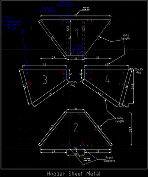
Hopper Sheet
- [1] 5'x10'x1/8" sheet
Other
- [6] 3”x3”x1/2” - cylinder mounts for both cylinders
- 2.5”x3/16” sq. tubing, 98" long, but 6" pieces - sleeves
- 1” shaft, 10” long - main cylinder mount
- 1” shaft, 6.5” long (shaker)
- 2”x2”x1/4” tubing, 3' long (2)
- 4”x4”x1/4” angle, 3' long (2)
- table – 1/8x10x28, and 12x28
- Hopper shaker assembly
- Magnet adjusters
- Cylinder adjusters
- Sensor mounting
