CEB Press/Manufacturing Instructions/Detroit Fab Lab Solenoid Driver
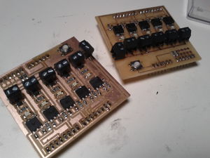
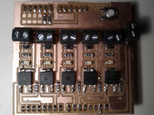
The Detroit Fab Lab has provided a custom-manufactured board that offers the five solenoid driver outputs required by the CEB Press. The card plugs into the Arduino Breakout Shield. The Five pins used to drive the five solenoid connections are as follows:
- D11
- D10
- D9
- D6
- D3
Here is some sample source code to test the five connections. Warning: Connecting the drivers to the solenoid unit incorrectly can ruin the unit. In particular, you should watch the polarity of the connections and ensure that opposite sides of one hydraulic circuit are not turned on by the solenoids at the same time. It is recommended that the board be fully tested first and then connected to the solenoid drivers. After this, circuit connections should be double checked before operating the solenoids.
int pwm_a = 11;
int pwm_b = 10;
int pwm_c = 9;
int pwm_d = 6;
int pwm_e = 3;
int i;

void setup()
{
//
   pinMode(pwm_a, OUTPUT);
   pinMode(pwm_b, OUTPUT);
   pinMode(pwm_c, OUTPUT);
   pinMode(pwm_d, OUTPUT);
   pinMode(pwm_e, OUTPUT);

   Serial.begin(9600);
}

void loop()
{

        fade_channel(pwm_a);
        fade_channel(pwm_b);
        fade_channel(pwm_c);
        fade_channel(pwm_d);
        fade_channel(pwm_e);
}

void fade_channel(int channel)
{
   Serial.println("Fading pwm channel to max: ");
        Serial.println(channel);

   for (i=0; i<=255; i++)
   {
      analogWrite(channel, i);
      delay(100);
   }

   Serial.println("pwm channel at max.");
        delay(1000);
        Serial.println("fading down.");

        for (i=255; i>=0; i--)
   {
      analogWrite(channel, i);
      delay(100);
   }

   Serial.println("pwm channel at 0.");
        delay(1000);
}
digikey parts
Bill Of Materials for CEB Press Driver Shield v1.0
Qnty Description Part # URL
- 5 Power N MOSFET RFD16N05LSM9ACT-ND http://search.digikey.com/scripts/DkSearch/dksus.dll?Detail&name=RFD16N05LSM9ACT-ND
- 5 Green LED 160-1169-1-ND http://search.digikey.com/scripts/DkSearch/dksus.dll?Detail&name=160-1169-1-ND
- 5 Diode 641-1331-1-ND http://search.digikey.com/scripts/DkSearch/dksus.dll?Detail&name=641-1331-1-ND
- 5 499 Resistor 311-499FRCT-ND http://search.digikey.com/scripts/DkSearch/dksus.dll?Detail&name=311-499FRCT-ND
- 5 49.9k Resistor 311-49.9KFRCT-ND http://search.digikey.com/scripts/DkSearch/dksus.dll?Detail&name=311-49.9KFRCT-ND
- 3 10k Resistor 311-10.0KFRCT-ND http://search.digikey.com/scripts/DkSearch/dksus.dll?Detail&name=311-10.0KFRCT-ND
- 6 2 Pos Terminal ED1514-ND http://search.digikey.com/scripts/DkSearch/dksus.dll?vendor=0&keywords=ED1514-ND
- 1 reset switch SW262CT-ND http://search.digikey.com/scripts/DkSearch/dksus.dll?Detail&name=SW262CT-ND
- 2 6 Pos Header A1913-ND http://search.digikey.com/scripts/DkSearch/dksus.dll?vendor=0&keywords=a1913-nd
- 2 8 Pos Header A1914-ND http://search.digikey.com/scripts/dksearch/dksus.dll?pname&site=us&lang=en&WT.z_cat_cid=Dxn_US_US2011_Catlink&name=A1914-ND
- 1 PCB 473-1002-ND http://search.digikey.com/scripts/DkSearch/dksus.dll?Detail&name=473-1002-ND
hints and tips
http://workmanship.nasa.gov/lib/insp/2%20books/frameset.html
http://en.wikipedia.org/wiki/PCB_Milling
http://reprap.org/wiki/Automated_Circuitry_Making
materials required
- soldering iron
- thin coreless solder
- rosin flux paste or liquid
- multimeter
- tweezers
- steady hand
- good eyes or a magnifying glass
board
- pcb etchant buy
- laser printer
- inkjet glossy photo paper
- acetone
- laundry iron
- drill press
- small drill bit #58 (1/16 is too big) buy
diagrams
steps
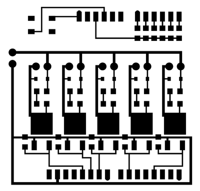
- make circuit board (you can mill the board or follow the instructions here to use a laser printer and etching)
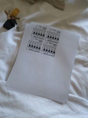
- print the mirrored image on laser photo paper
- tape the paper onto the copper board
- using a laundry iron, heat the paper until discolored
- soak in water and peel the paper away
- agitate in pcb etchant solution for 20-30 min until copper is gone
- using a #58 drill bit and drill press, drill all the holes
- apply accetone to a cloth and wipe away toner
- check and fix errors
- places where not enough was etched away or where too much was
- soldering
- plan ahead
- start with the smallest and shortest parts
- apply flux to one of the copper sides
- put a little solder on the tip of the iron and apply a little solder to that side
- apply flux to both sides
- hold piece in place on top of the solder
- for the diodes, leds, and swtich, double check the orientation
- while holding in place with gentle force, tap the iron onto the solder already on the board
- visually confirm the connection and placement
- apply flux to the other side
- add solder to the iron and connect the other side
- repeat
- it helps to do each step for multiple components, making progress on them as a group
- plan ahead
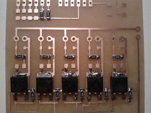
- mosfets
- apply flux to the two copper leads and the large copper square
- add solder to the iron and apply to the two leads
- place and hold the mosfet
- while holding in place with gentle force, tap the iron onto the solder already on the board, connect one lead and then the other
- take care to align correctly, it is difficult to turn once two leads are attached
- optionally add more solder to the leads
- flux and solder the other side to the copper square
- a heatsink may be prudent here
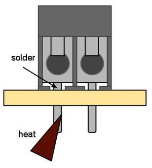
- terminals
- flux on the base
- push the terminal through its holes, but keep it elevated a little
- place your iron in the gap at the front of the terminal, pushing down on the board
- feed solder from the side
- repeat
- reset switch
- wait till after the headers to do the switch so it wont be in the way
- headers
- the home stretch
- using an exacto knife clean out the holes from the bottom
- push posts through and solder
- heat the posts from below using a high power iron and feed solder into the front of the header at the surface of the board.
- test
notes
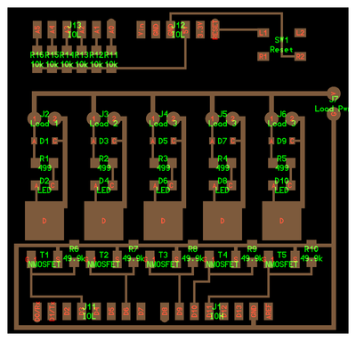
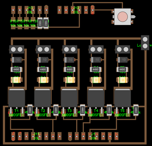
orientations with switch at top:
- diode - grey stripe on left
- led - green stripe on left
- switch - metal part reaching to base is on the right
4992 resistor = 49.9k Ohm
4990 resistor = 499 Ohm
1002 resistor = 10k Ohm
Assistance
- OSE Forum - http://forum.opensourceecology.org/discussion/520/replication-assistance-detroit-board
- Tutors
updates
- get rid of reprap breakout board
