Hydraulic Power
Most OSE machine technology relies on hydraulic power, which requires a hydraulic pump powered by an engine. This page contains information on hydraulics.
See Also Hydraulic Motor, Hydraulic Fluid
Introduction
Hydraulic power systems transfer energy through the flow of a pressurized liquid - most commonly a petroleum oil with a few additives. Hydraulic systems use a high-pressure pump to recirculate the working fluid from an unpressurized reservoir through high-pressure hoses, pipes, and control valves to actuators (motors or cylinders), and then back to the reservoir.
The strong points of hydraulic systems are:
- pumps and motors are compact and lightweight for the amount of power they handle, i.e. high power density
- high force linear movement is easily produced with a minimum of moving parts (hydraulic cylinders)
- basic control (manual and solenoid valves) is simple to implement
Because of their high power density and ruggedness, hydraulic systems are essential for mobile equipment like earthmoving and farm machinery. Hydraulics also find niche applications in airplanes, industrial robots, and other machinery. A wide variety of actuators, valves and other control devices are available to perform specialized tasks in hydraulic systems.
In stationary industrial equipment, hydraulic systems are often replaced by electrical or pneumatic power systems. Some of the weak points of hydraulics are:
- inefficient (unless more costly and complicated designs are used), leading to wasted energy and overheating issues
- requires continuous filtration to protect pumps, motors, and valves from damage
- prone to leakage
- controls can become complex (if anything more than on/off, one-function-at-a-time performance is required)
- difficult to distribute power over long distances
There is a (U.S.) National Science Foundation research program exploring improved hydraulics: CCEFP.
In the GVCS, the modularity goal argues for Stationary Hydraulic Power, so that the same equipment can be used either in a shop building or in the field. This is much less common than stationary pneumatic power ("Shop Air").
Information
Educational Resources - Lots of links by the Center for Compact and Efficient Fluid Power
Fluid Power e-books - Great online e-book resource covering almost all aspects of fluid power
Purdue Fluid Power Open Courseware - For serious open-courseware, college-level hydraulic engineering from Purdue University
Hydraulic Supermarket - Resource for links to products and learning resources
Physics Archives and extensive overview
LifeTrac Hydraulics Primer
LifeTrac has a 55 horsepower diesel engine. It powers a 29 gpm, 3600 psi hydraulic pump. The pump RPM must be matched to the engine RPM. PSI (pounds per square inch) is a unit of pressure, defined as force per area. This pump provides the high pressure fluid flow to the entire tractor. The hydraulic fluid powers every single aspect of LifeTrac - wheels, turning cylinder, front end loader, power take off generator, auxiliary power outlets.
The basic principle of fluid flow is continuity of flow. This flow starts with the engine, which powers the hydraulic pump. The pump is pumping fluid at all times that the engine is turned on. There is no way to disengage the pump - the pump is always on and pumping. Therefore, the fluid must have a path to make a complete circuit. The pump takes fluid from the reservoir, which then passes through the pump and can attain 3600 psi of pressure under load. This fluid must circulate back to the reservoir to complete the continuous cycle through the pump.
Continuity of flow requires that if a valve is engaged or not engaged - fluid must have a path to flow in both cases. If it doesn’t, the engine stalls (typical at low throttle) or bursts a hose (possible at high tractor throttle). If a valve is disengaged, fluid flows right through the valve and back to the reservoir. If a valve is engaged, fluid flows through the working device and then back through the valve and then back to the reservoir.
Continuity of flow has a fundamental effect on all tractor operations. For example, if the wheel control valve is engaged suddenly, the wheels spin out and burn rubber in typical conditions. This is because a rush of fluid suddenly enters the wheel motors - and because the 55 hp engine suddenly transfers all its power to the wheels, the wheels spin out.
For the reason of sudden fluid flow onset to the wheels, a cushion valve is installed. Instantaneous flow to the wheels can mean that the hydraulic pump may put out more than its rated 3600 psi - since the engine has a flywheel and inertia. Even if pressure does not exceed 3600 psi - the cushion valve serves to bypass fluid to the return line, providing a smooth start. It also allows fluid to circulate through the wheel motor upon stopping, therefore smoothing out tractor motion upon stopping. In general, the cushion valves smooths out bumps - such as hitting an obstacle in the road - by letting fluid bypass accordingly.
Dedicated wheel control valves, which can vary flow smoothly from closed to open - are recommended for the wheels for smooth starting. Presently, we have plain on-off control valves.
Continuity of flow has serious effects on loader operation. If a heavy load is being lowered on the front end loader, and the valve is closed suddenly, a major shock will occur due to the inertia of the lowering load. This can cause damage to the tractor in extreme conditions - such as the tractor snapping in half. The shock occurs because fluid flow is stopped suddenly, so the lowering motion is locked instantly. This causes the shock. This shock has been eliminated with the use of a cushion valve on the front loader circuit.
Flow continuity must be considered carefully when operating spinning rotors with high inertia. This is the case with the PTO portable generator, which has about a 300 pound rotor spinning at 1800 RPM. If the valve to this motor were turned on suddenly, there would be pressure release occurring through the valve - assuming that we are working with valves with built in pressure releases. Upon turning the valve off suddenly, major damage would occur, most likely to the PTO generator. A valve that is turned off allows no fluid back into itself from the working device. If the PTO generator valve would be turned off, then all the inertia of the PTO generator would be transferred to the fluid - as any motor also functions as a pump when it is not being driven. This would either blow the hose or rip the PTO generator rotor right off its shaft. For this reason, we installed a check valve that can circulate fluid freely through the hoses when the PTO generator is spinning down.
For the sawmill, we will use 2 of the 3 auxiliary hydraulic outlets with quick connects. We can consider a single motor to the main cutting blade, and another motor to the edger blades. We can consider setting the pressure relief on the auxiliary valves (what is the pressure rating?) to the max, to drive more powerful hydraulic motors. We need to match the pressure rating of the valves to the motor - in which case we may consider purchasing dedicated valves and motors.
We have 24 gpm available from after the steering cylinder flow divider - such as at the 3 auxiliary power take-off valves. We can also tap in our sawmill before that point, where we have 5 more gpm available. If we tap at the auxiliary outlets, we need to remember that the quick couplers are rated for only 12 gpm each, so we need to use multiple outlets.
Questions:
1. Calculate the force obtained from a 2.5” hydraulic cylinder operating at 2000 PSI.
2. What is the minimum PSI rating requirement for the outlet hose from the pump for regular operating conditions?
3. If the 3/4”outlet hose from the pump is to resist bursting upon being plugged suddenly for some reason, what PSI rating is suggested for the hose?
4. What is the power output of a hydraulic motor rated at 25 gpm and 3600 psi?
5. How well is our hydraulic pump matched to the diesel engine, both in power and rpm?
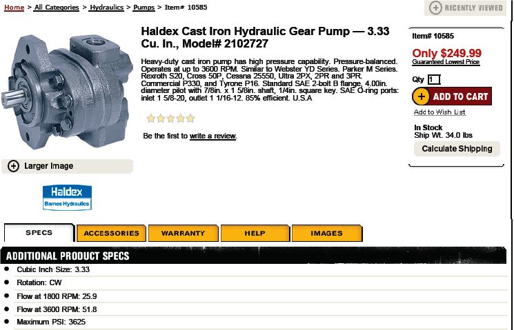
LifeTrac has this pump from Northerntool - [1]:
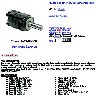
All hoses are already available - it is part of our flexible open source tractor infrastructure. Here are the motor specifications, from Surpluscenter.com:
Available Power
- Review of LifeTrac hydraulic power calculations - LifeTrac#Calculations - shows that we have total 29 gpm available at 3300 PSI, or a lower flow at 3600 PSI.
- Hydraulic power is defined as Flow x Pressure. The hydraulic power supplied by a pump: P in [bar] and Q in [lit/min] => (P x Q) / 600 [kW]. Ex. Pump delivers 180 [lit/min] and the P equals 250 [bar] => Pump power output = (180 x 250) / 600 = 75 [kW]. 75000W / 745.7 = 100.58hp
- LifeTrac has 91 l/min available from the auxiliary hydraulics, and 228 bar - 91x228/600/.746 = about 46 hp.
               + 24 gallons/minute = 91 liters/minute (of 29 gpm total LifeTrac power, 5 is diverted into tractor steering)
               + 1 bar = 14.5 psi, 3300 PSI = 228 Bar
Hydraulic Power
Engines
- [[2]]
Pumps
Power Packs
- 16 HP Hydraulic Power Pack $5,861.14
- BVA Hydraulics 10,000 psi gasoline engine driven hydraulic pump. 5 gallon reservoir. 2 stage operating action. 4 way, 3 position manual valve, 5.5 HP Honda engine. Protective roll bar. $3,307.40
- Wisconsin 37 Hp Gas Powered 3000psi Portable Hydraulic Power Pack
- Sunstrand hydraulic power pack, 25 hp, 3/60/230/460 volt,1770 rpm XP motor. $2,625.00
Hoses
- Hose flow ratings based on hose size - [3]
Hydraulic systems
Motors
Calculations
- Hydraulic motor power from PSI and GPM - [4]
- Ex - 12 gpm at 2000 psi is 14 hp. Does this match another way to calculate [5]?
- Try in-lb*rpm/63k = 12 hp.
- Simply put: take 2000 PSI, multiply by GPM - and that is your actual horsepower. However, the pump formula from PSI & GPM accounts for inefficiency pof 15%, so the PSI & GPM formula gives a higher answer, corresponding to the actual pumping.
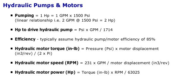
Hydraulic Pumps & Motors
- Pumping = 1 Hp = 1 GPM x 1500 Psi
(linear relationship i.s. 2 GPM @ 1500 Psi = 2 Hp
- Hp to drive hydraulic pump = Psi x GPM / 1714
- Efficiency - typically assume hydraulic pump/motor efficiency of 85%
- Hydraulic motor torque (in-lb) = Pressure (Psi) x motor displacement
(in3/rev) / (2 x Pi)
- Hydraulic motor speed (RPM) = 231 x GPM / motor displacement (in3/rev)
- Hydraulic motor power (Hp) = Torque (in-lb) x RPM / 63025
Software
http://www.comatrol.com/easyvalve
http://qdlite.sunhydraulics.com/login.aspx
cad models
http://www.eaton.com/Eaton/ProductsServices/Hydraulics/Tools/Eaton3DCADLibrary/index.htm
See Also
- Section of the Open Source Motor/Engine Construction Set dealing with hydraulics
- [6]
- book
- chart - flow through orfices
- Calculations for Pump Sizing
- Hydraulic machinery: with an introduction to hydraulics
- 9-dumb-mistakes-people-make-designing-fluid-power-systems
- design-concepts-for-open-circuit-architectures


