Stationary Hydraulic Power
Introduction
A stationary hydraulic power installation is similar to a "shop air" compressed air system. Typically a central power unit (pump) provides pressurized hydraulic fluid to a plumbing system, which distributes it to multiple points of access around a machinery installation or a building. In the early 20th century municipal hydraulic power flourished in London, and dockyards often had substantial stationary hydraulic installations. While this type of installation is relatively uncommon in current practice, it has potential advantages in the GVCS ecosystem. This page is an exploration of stationary hydraulic power implementation issues.
Benefits
- High peak-to-average-power loads are easily handled
- Hydraulic energy can be efficiently stored for load leveling
- The same hydraulic-powered tool with quick-connect hose fittings can be used
- Shop tools benefit from the high power density of hydraulic actuators
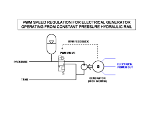
It is also fairly simple and efficient to drive an electrical generator from a hydraulic motor, possibly with a switch-mode hydraulic control for speed regulation. See also Steam-Hydraulic Electrical Generator
Design Principles
Constant Pressure
In contrast to simple mobile hydraulics (like the LifeTrac design), a stationary hydraulic power system must support a number of independent tools which can be running simultaneously (e.g. used by different people) without interfering with each other. This requires a constant-pressure, variable flow system, rather than the constant flow approach which is common in small mobile machinery.
Constant-Pressure pump systems
The most common industrial approach to making a constant-pressure hydraulic power unit is to employ a variable-displacement pump driven by a constant-speed electric motor. Vane pumps, and axial piston pumps (with adjustable swash plates), are popular designs. However, alternative approaches are possible, including
- fixed-displacement gear pump on a variable-speed motor
- cyclic (on/off) pump action charging a pressure reservoir ("hydraulic accumulator")
- this is similar to an air compressor cycling on and off to keep a shop air tank up to pressure
- a continuously-running gear pump may be intermittently connected to the accumulator, through an automatic valve under pressure-sensor control (this is similar to an "unloader" valve commonly used on large shop air compressors). A standard Powercube can be connected in this mode.
- A steam engine with variable valve timing can adapt its output speed and power dynamically to a varying hydraulic system load.
- A free-piston engine is particularly appropriate here
Hydraulic Accumulator Function
A hydraulic accumulator is an energy storage device. Several styles of operation are possible, depending on the amount of stored energy (which may be expressed as the number of minutes of operating load contained in the accumulator).
- Large storage (hours of operation)
- Small storage (minutes of operation)
- Pulse absorption (seconds or less)
Large storage
Large storage applications may be compared to the battery banks used in solar electric systems, which carry the operational load when the sun is unavailable.
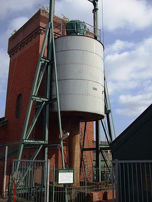
Hydraulic accumulators have much lower energy density than electrochemical batteries, so a huge device is needed. Historically, the most practical devices for this purpose have been raised-weights, which are a very simple technology. Compared with batteries, this can also be quite efficient: there is effectively zero self-discharge loss, and charge/discharge losses are limited to seal friction in the lifting cylinder. Operating at a 20-ft lift, a raised weight stores 2 horsepower-hour per 100 tons; a 100-ton cube of concrete is about 11 feet on a side. (The same 2 hp-hr could be stored in about 100 lb of lead-acid storage batteries).
Early stationary hydraulic systems most commonly operated with water at around 50 atmospheres (700 psi), a pressure range similar to modern oil-hydraulic passenger elevators. Elevator cylinders ("jacks") are commonly made up to 50 ft or so in length. For the GVCS ecology, it would be desirable to operate at a higher system pressure, perhaps 2000psi.
A raised-weight accumulator can be supported on several small-diameter cylinders with an aggregate piston area adequate to support the weight at nominal system pressure. This type of design is quite modular, as capacity can be added
- by fitting more cylinders and adding proportionately more material to the weight
- by stacking cylinders in series (increase the lifting distance)
- by connecting additional modular accumulator capacity -- simply a cylinder and weight -- at any location in the hydraulic distribution system.
As with any installation capable of storing considerable energy, the potential for dangerous accident should be considered. The collapse of a raised-weight structure is a relatively benign failure, compared to a compressed-gas explosion, for example.
Small storage
Small storage applications apply to systems where prime-mover capacity (e.g. a steam or internal-combustion engine) is available to carry an intermittent operational load, but takes some time to start and come on line. In this situation, the accumulator serves the function of spinning reserve of electrical utilities. Small storage accumulators are also very important in the very common situation where the prime mover does not have the capacity to handle peak load but can support the average load.
High peak-to-average loads arise both directly (e.g. CEB, drill press) and indirectly (e.g. hydraulically-driven electrical generator powering an arc welder).
In a small-scale installation, the hydraulic system is often completely idle. When the system is in "standby" (nobody is using hydraulic power at the moment), the lines remain pressurized. If there is no major leakage, the main pump can be turned off and the accumulator will maintain pressure. When a tool is connected and fluid begins to flow, the pump will turn on. A small-storage accumulator can seamlessly provide hydraulic power while the pump starts up. The pump turn-on can be triggered by a pressure drop or by an accumulator-capacity sensor.
For these applications gas-bladder accumulators are at least as suitable as raised weights. The compressed-air/hydraulic "open accumulator" achieves much higher energy density than a gas bladder with a tradeoff in increased complexity.
Pulse absorption
Hydraulic shock and surge loads arise from valves that open or close quickly or actual mechanical shocks that are part of the tool operation. It is helpful to isolate the main distribution system from these shocks, which can cause momentary peaks or dips in pressure to other tools, higher frictional flow losses, and extra stress on the distribution piping. Small gas-bladder accumulators located close to the tool (either incorporated at the tool itself, or at the quick-connect outlet it is fed from) serve this need.
Constant-Pressure Tools
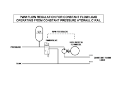
For use on a constant-pressure shop supply, a tool's flow path should be blocked (no flow) when it is not in use. In contrast, on a constant-flow mobile system, a subsystem's flow path is open, through the "power beyond" valve gallery to tank return, when it is not in use. This is a concern for tools which incorporate their own valving; for example, it may be necessary to make a porting change in order to connect a CEB Press to the constant-pressure shop supply line. On the other hand, a simple actuator which connects to the LifeTrac hydraulic takeoff (and expects to be controlled by the LifeTrac HTO control valve) will operate equally well from an appropriate "shop" control valve connected for constant-pressure supply.
Hydraulic pressure transformation
In most multi-circuit hydraulic applications, efficiency is poor because the operational cycle requires the load pressure and load flow to vary widely, but the prime mover/pump can only be optimized for a single pressure/flow operating point. Efficiency is improved with load-adaptive pumps (variable displacement, load sensing circuits). However this technique optimizes dynamically to a single circuit's load and does not scale to many circuits driven by a single pump -- the situation in a constant-pressure stationary hydraulic power distribution system.
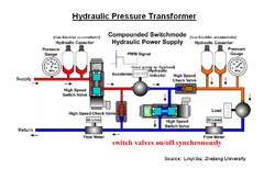
Efficiency and other benefits accrue with the availability of "hydraulic transformers" which convert input hydraulic power at one pressure/flow level to hydraulic output power at a different pressure/flow level; this is most useful when the transformation ratio is dynamically adjustable. Four approaches are:
- piston intensifier (fixed transformation ratio): pressure applied to a large-area piston pumps fluid from a small-area piston, typically using a "stepped" piston with two different diameters.
- pump intensifier (fixed transformation ratio): a fixed-displacement hydraulic motor drives a fixed displacement hydraulic pump where there is either a different displacement per revolution or a mechanical gear ratio between the motor and pump
- "reverse hydrostatic drive": a hydraulic motor drives a variable-displacement hydraulic pump.
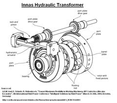
- this proprietary hydraulic transformer made by Innas
- switch-mode hydraulic transformer like this from Cao et al [1], [2] in China
Note that the last two approaches are relatively new (less than a decade old).
A switch-mode hydraulic transformer may be an effective way to operate constant-flow ("open-center"-design) tools from a constant-pressure stationary hydraulic power system.
