LifeTrac Manufacturing Instructions
Introduction
As of December 27, 2011 - we are currently working on LifeTrac Prototype IV - which features bent loader arms and Quick Connect Wheels. The new loader is File:Loaderbent.pdf. When the new wheel motors and loader arms are tested, they will be added to the official CAD. For now, we recommend replication of only the frame, unless one is a dedicated developer.
The difficulty with the motor shafts breaking involved the mislabeling of the hydraulic wheel motors by surplus center, where we discovered that the motors were simply not rated for the pressure that we used. The tractor can be built as is by replacing the wheel motors with stronger 15,000 Inch Pound Motors. The straight loader arms have poor weight balance, so we recommend building the bent loader arms of File:Loaderbent.pdf instead. These can be built by leaving the arm pivot exactly as it is, with a cut in the arms followed by welding on gussets. These arms will be optimized in the future. The quick connect wheels appear to be a robust solution.
Documents
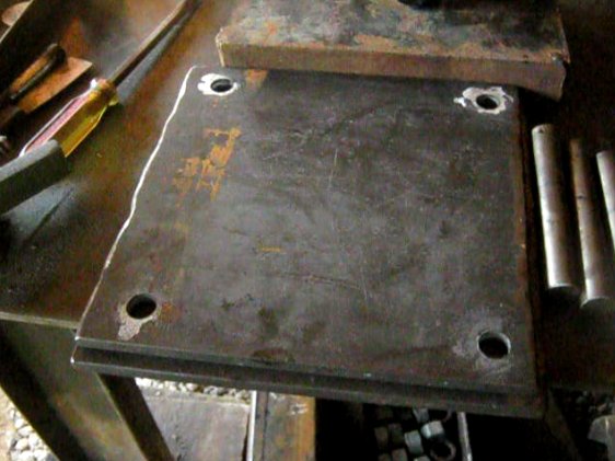
- Computer Aided Manufacturing (CAM) Files are available for the various mounting plates. See Tractor CAM files – wheel, bearing, and motor mount plates.
Parts Manufacture
Frame
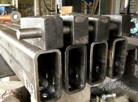
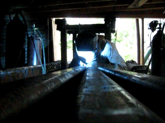
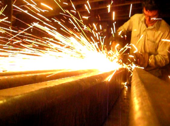
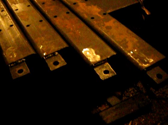
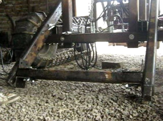
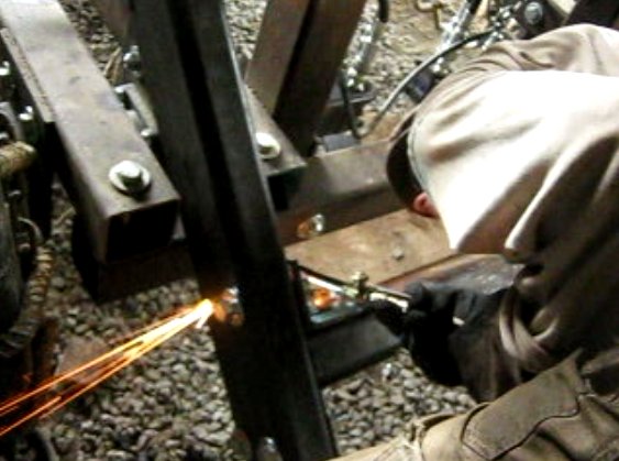
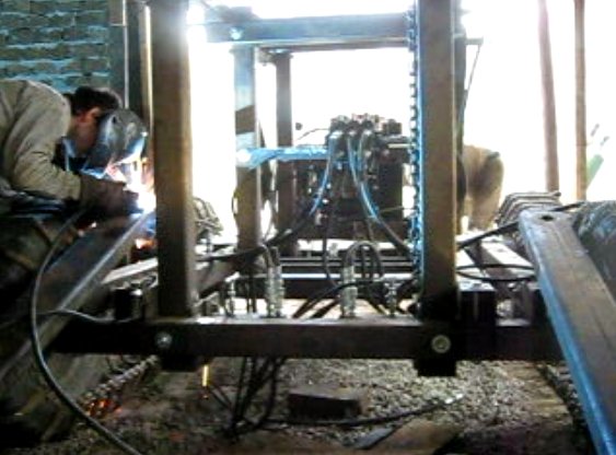
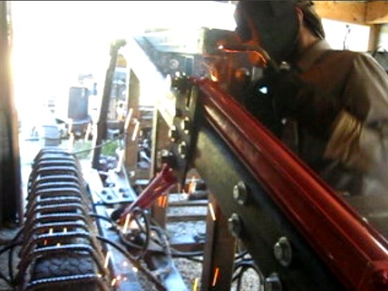
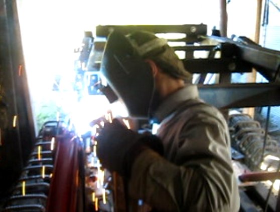
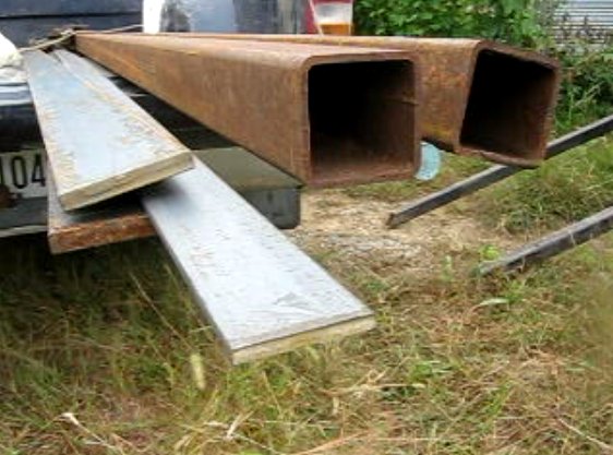
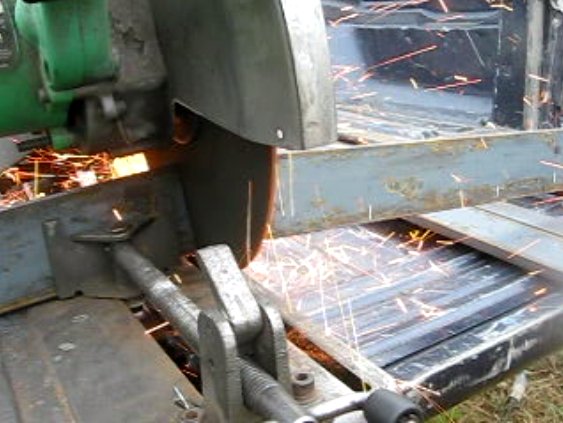
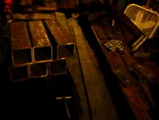
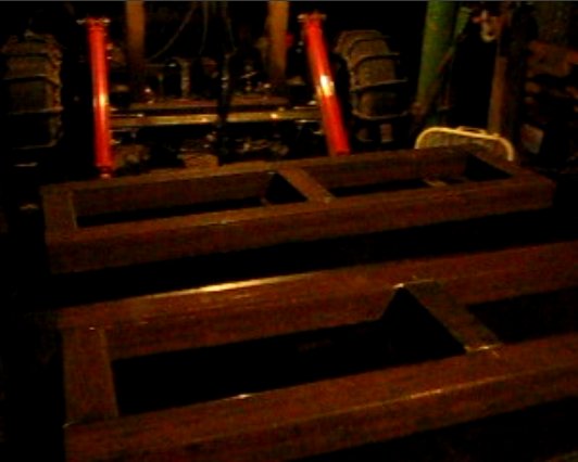
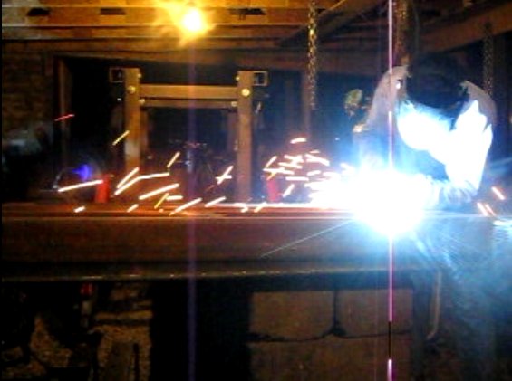
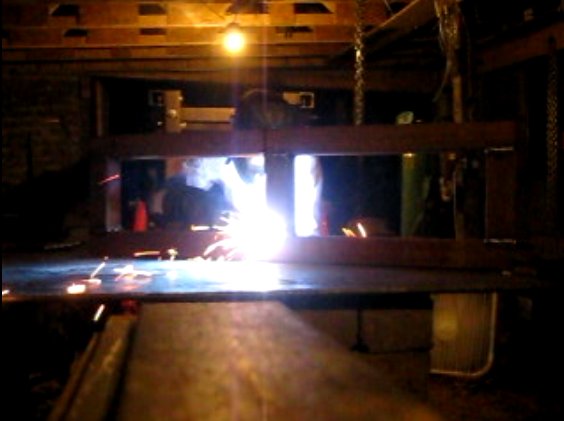
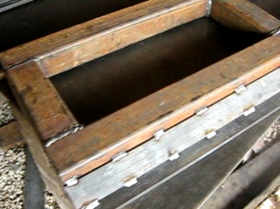
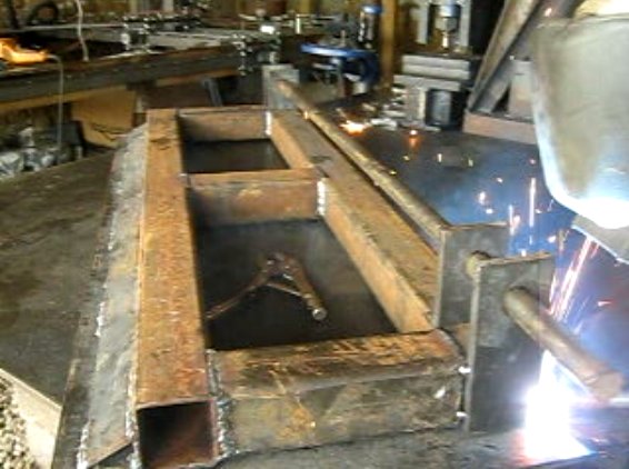
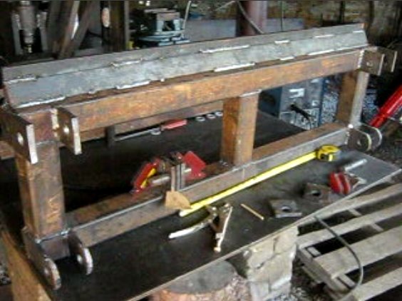
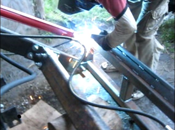
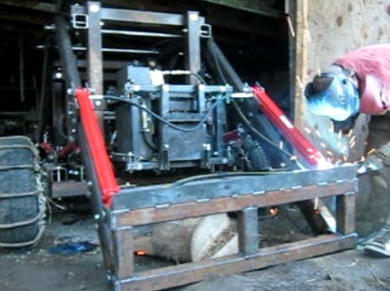
Then, build the frame.
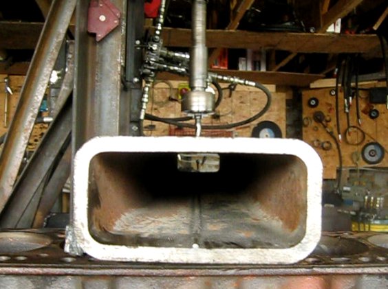
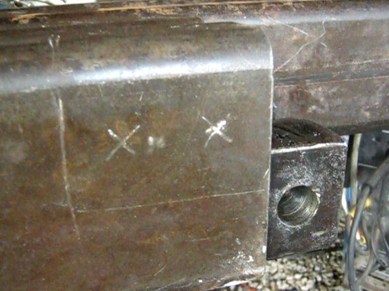
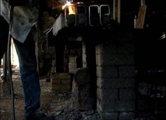
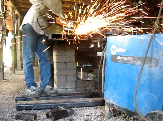
Frame Construction Video Script [[1]]
Updated frame video:
Wheels
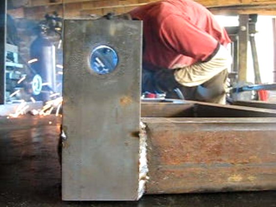
Wheel Assembly Video Script [[2]]
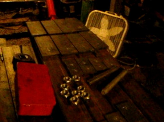
Then, prepare all the wheel mounting materials.
Then add the wheels (from Sean Church):
Lifetrac II- Wheel Mounting from Sean Church on Vimeo.
Then, go for the first test drive.
LifeTrac II Test Drive from Marcin Jakubowski on Vimeo.
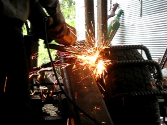
Wheel Tracks
Wheel Tracks Construction video script [[3]]
Then, [build the wheel tracks.]
Extreme Traction from Marcin Jakubowski on Vimeo.
LifeTrac Hydraulics
See blog spot
LifeTrac Valves from Open Source Ecology on Vimeo.
Loader Arms
Then, build the loader arms - both front and rear.
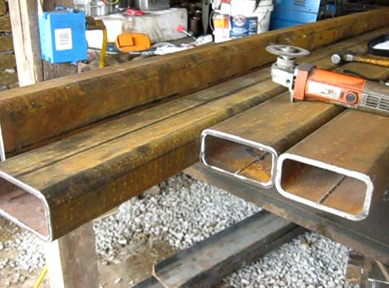
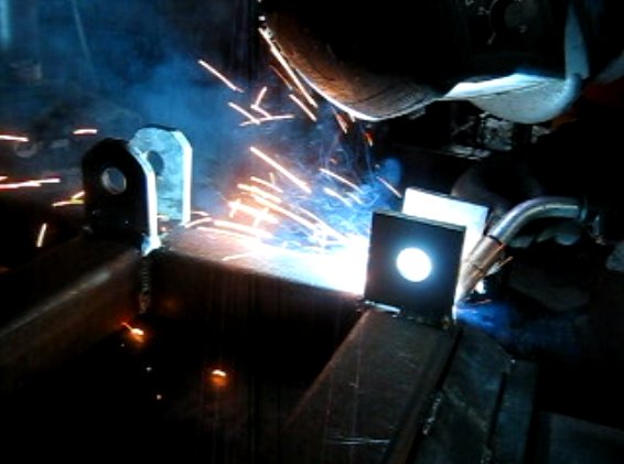
1. Prepare loader arms.
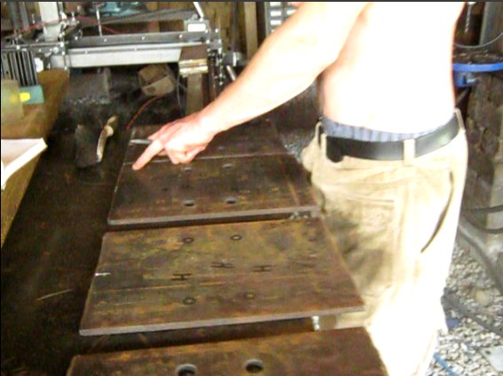
2. Mark loader attach plates for hole locations.
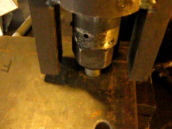
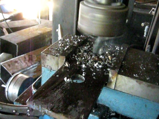
3. Punch or drill mount plate holes.
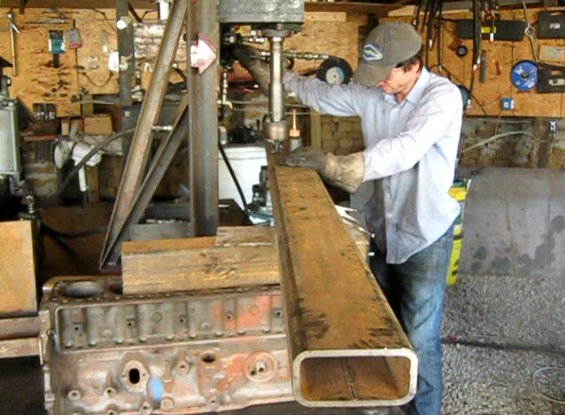
4. Drill holes in loader arms.
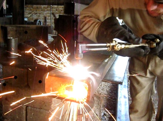
5. Torch out arm mounts
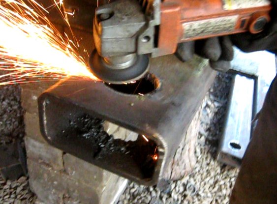
6. Grind arm ends.
7. Drill or punch 1" holes for cylinder mount bottoms.
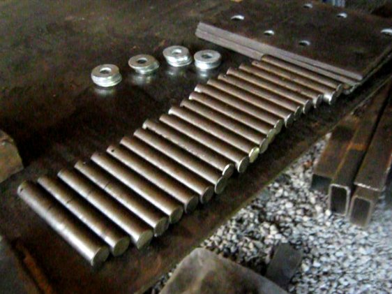
8. Cut pins to size.
9. Prepare bottom mount plates for loader arms.
10.Torch out 2" inserts.
11. Mark arm locations on frame.
12. Grind 2" inserts.
13. Drill 1" hole in inserts.
14. Torch out holes in frame for loader arms.
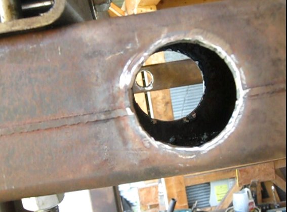
15. Smooth out holes for loader arms.
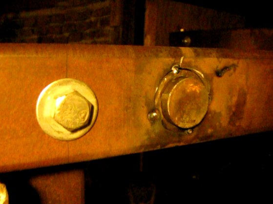
17. Fit shafts and DOM bushing for laoder arms.
18. Finish inserts.
19. Drill rear loader arms.
20. Mark loader arms for insert plug welds.
21. Torch out plug weld holes.
22. Grind plug weld holes.
23. Line up plug inserts for welding.
24. Plug weld inserts.
25. Grind plug welds.
26. Finished inserts.
27. Weld arm gussets.
28. Arm gussets plug welded.
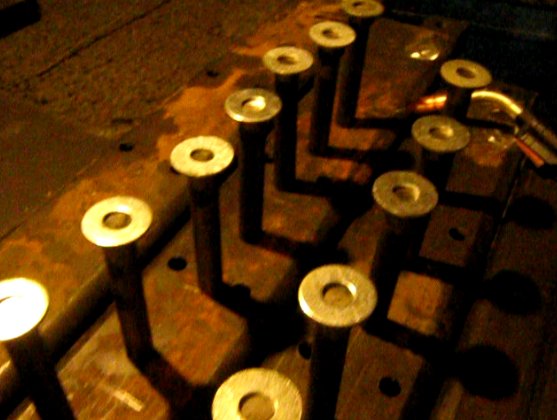
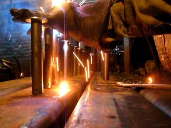
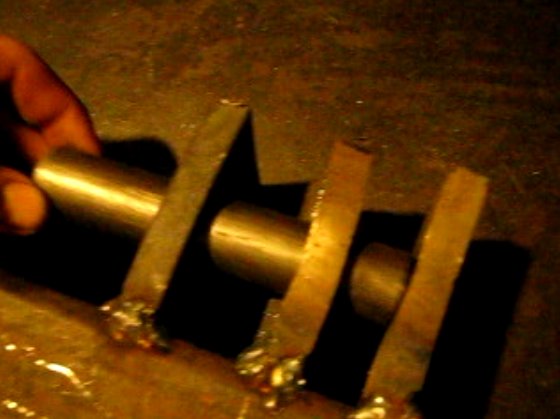
29. Prepare pins for welding.
30. Weld pins.
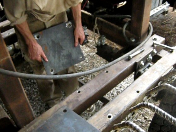
31. Mount cylinder base plates.
32. Mount cylinder plates to arms.
33. Mount cylinder cross support.
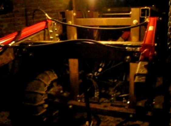
34. Mount cylinder arms on frame.
35. Arm cross supports.
36. Put on real loader arms.
37. Hang arm cross support.
38. Torch misfit holes.
39. Weld inner arm gussets.
40. Grind inner arm gussets.
41. Finish attaching cross supports.
42. Finish weld arms.
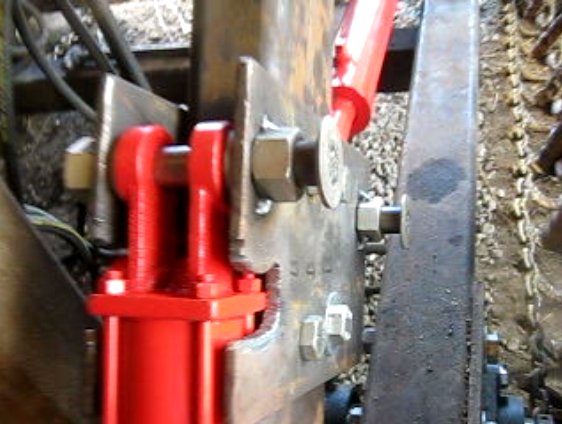
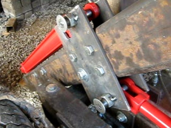
43. Bolt cylinder attach plates.
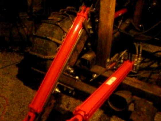
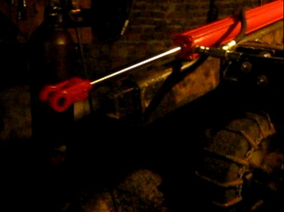
44. Attach cylinders.
45. Mount quick attach (QA) plate cylinders.
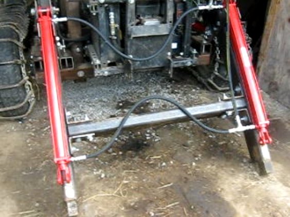
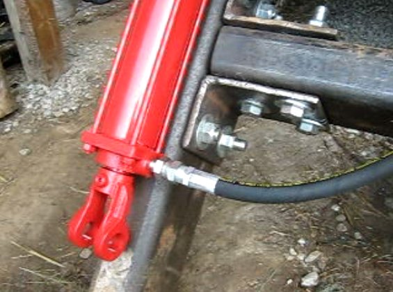
46. Begin attaching hoses.
47. Hose attachment.
48. Tack weld gusset nuts.
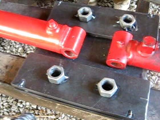
49. Tack weld bottom cylinder support nuts.
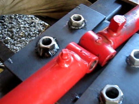
49.5. Tack weld cylinders.
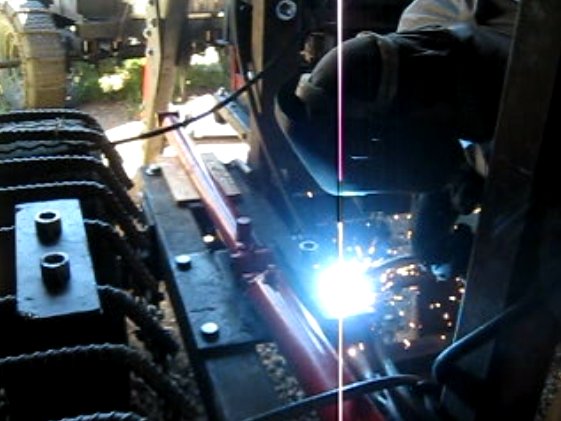
50. Complete bottom cylinder gusset welds.
51. Botom cylinder gusset nuts welded.
52.
52. Finish weld top cylinder.
Quick Attach Plate
60. Prep QA plate materials.
61. Cut stock to size.
63. Cut all tubing to size.
64. Mark hole locations for all pieces.
65. Hole punch all pieces.
66. Prepare QA plates for welding.
67. Weld QA frame.
68. Finish welding QA plate.
69. Weld fingers.
70. Weld bottom eyes.
71. Finish weld bottom eyes.
72. Weld top eyes.
74. Begin on QA mechanism.
75. Finish weld eyes in place.
75.5
76. Finish weld eyes.
77. Raise arms.
78. Extend QA cylinders.
79. Fit pin in QA mechanism.
80. Mount QA plate on arms.
81. Extend QA plate.
82. Weld pin pushing mechanism.
83. Weld handle to rotation pin.
84. Mark rotation pin location.
85. Mount handle and push pin and bolt down.
86. Put on stops and set screws.
87. Do same for second set of loader arms - and LifeTrac II with front and rear loaders is ready for testing.
Quality Assurance
Now take tractor for a test drive:
LifeTrac Prototype II Completed from Marcin Jakubowski on Vimeo.
See corresponding blog post - http://blog.opensourceecology.org/2010/09/lifetrac-prototype-ii-completed/
