PCB Mount
Is this for milling, or is this a non-conductive / anti-static mat for electronics work?
Introduction
A PCB Mount firmly holds a PCB. The PCB Mount itself attaches onto an electronics case.
A PCB Mount should:
- Prevent the circuit from contacting conductive material.
- Transition from the PCB's mounting interface to the PCB Mount's mounting interface.
Action Info
1/4" x 12" x 24" HDPE Natural White
Cut to size, drill pre-tap holes, then tap those holes!
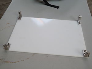
Mount the HDPE plate inside the Terminal Case by using compression against the walls of the case. Use thread for higher torque from rotary-to-linear conversion. Use rubber or other high-friction, vibration-damping, electrically insulating material for reliability, continuous shock resistance, and EMP protection.
Drill and tap 1 hole near the end of an aluminum flat bar and drill (no tapping) 2 holes near the other end. Bend the aluminum flat bar into a 90 degree angle. Match drill the 2 holes into the HDPE, tap the HDPE, then mount the angle to the HDPE with screws. Mount a screw inside the 1-hole to use as the compressor piece. Place the HDPE inside the case and tighten the compressor screw to compress against the walls.
Instead of bending flat bar, cutting aluminum angle at 45 degrees then TIG welding the angles together at 90 degrees provides more rigidity to the entire compressor frame.
Mounting Interface
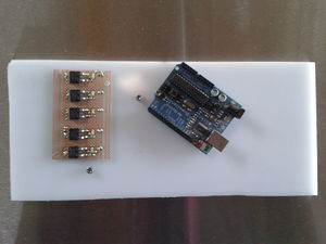
The PCB likely will have mounting holes in a unique pattern for that particular PCB. The PCB Mount should be fabricated to have the same mounting hole locations as the PCB, but the holes having thread so as to be able to screw the PCB to the PCB Mount from the top.
The PCB Mount also needs to mount onto the electronics case. Tension against the inner surfaces of the electronics case is effective especially for waterproofing, modularity, and ease of assembly/disassembly.

