Poka-Yoke
About
A poka-yoke is any mechanism in a lean manufacturing process that helps an equipment operator avoid (yokeru) mistakes (poka). Its purpose is to eliminate product defects by preventing, correcting, or drawing attention to human errors as they occur.
In OSE's case, it is a physical feature on a build object that allows assembly only in one way - a mistake is physically difficult or impossible to make.
The physical feature may be a structure, or a mark. For example, a simple line drawn on an object - which aligns with another line - can be a poka-yoke feature. Color coding can serve as poka-yoke. Bins or sets of tools/materials can be poka-yoke mechanisms. The concept can be generalized to just about anything that allows for a tangible check against human error. The limit of poka-yoke as one uses more advanced tooling is Digital Fabrication and Computer-Aided Assembly.
Poka-Yoke in CAD
Advice from Rob B.
- the main goal is to get a .dxf file exported that you can send to the manufacturer who is going to cut the plate. I tried doing some dxf exports out of freecad a long time ago and had some trouble, but I'm sure things may have changed since then. Most CNC cutting tables are able to import 2d DXF files.
- I assume that you'll probably have someone cut these using plasma, laser, or waterjet, or acetylene cutting. how much tolerance or clearance you allow for yourself between finger and slot will depend on cutting method. for plasma and torch cutting, you will want to allow maybe at least around 1/16in-1/8in clearance so the parts fit together. If parts are lasercut or waterjet, you can go a little tighter, maybe 1/32in-1/16in clearance between parts. I would have to look back at my drawings to see how loose of a fit I allowed myself for plasma cutting.
- Also, you might see from some of my old parts how I made a relief cut so that the parts nest into each other without corners interfering. Cut plate always comes out a lot more rough, tapered, and rounded than the perfectly square shaped cad drawn lines.
- the way we did it last time, when some parts fit together, there is a big 1/8in gap that can be filled in with weld. That seemed to work out well.
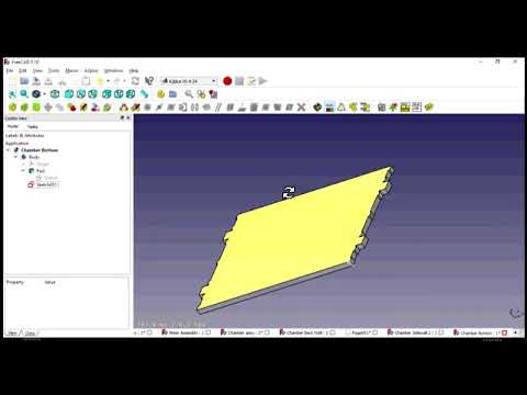
Poka-Yoke in FreeCAD
Adding Fingers and Slots Retroactively
Using Sketches
The following video shows one method to use the symmetry tool in the sketcher workbench to quickly add fingers and slots to the parts.
http://img.youtube.com/vi/Ukx1YaECgTE/0.jpg
Using Part Features
Example file: File:MirrorPartFingerSlot.FCStd