Quick Connect Wheels
These were posted as a GrabCAD Design Challenge in Dec. 2011 - http://grabcad.com/challenges/lifetrac-quick-connect-wheels
See also Bulldozer Specification
Update of July 14, 2015
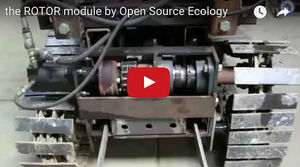
Example of Universal Rotor Unit on micro tractor:
Update on February 3, 2012
(note: the following CAD file was lost in a computer crash. The only existing CAD is in the Google Warehouse link)
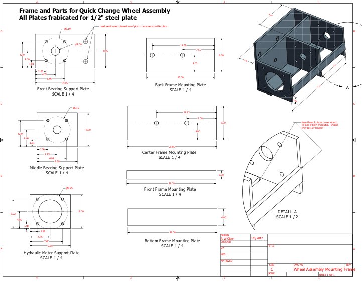
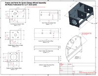
Source: File:Qcwheelfab.pdf
Notes: reduce the 7.5, 14.63, 7.0, and 14.13 dimensions in the two horizontal plates by 1/2" since a 1/2" spacer on the outer frame member (formerly for 2 peg holes, which were eliminated and replaced with 1/2"x2" stops) has been eliminated in a newer design. The new dimensions should be 7.0, 14.13, 6.5, and 13.63. The length of the top plate should be reduced from 16" to 15.5", and corners should be cut off to allow the cam to turn.
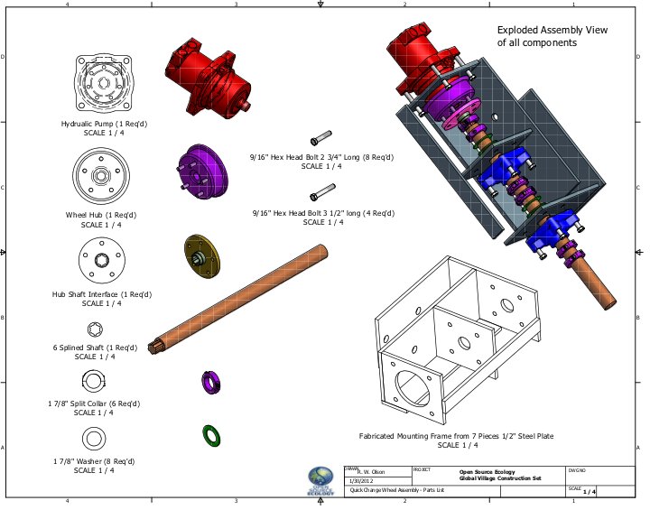
Source: File:Qcwheelfabparts.pdf
Update January 27, 2012
Prototype #3 - double chain sprocket coupler. Advantage: larger radius to withstand 15,000 inch pounds of torque
.
.
Update 1/15/12
Fab drawing - File:Qcwheelfab.pdf
Update 12.24.11
Prototype in progress, using 15,000 Inch Pound Motor - promising results:
.
.
Introduction
LifeTrac wheel couplers suffered catastrophic failure when used with tracks - October 2011.
.
The key on the motor shaft sheared. We put on thicker couplers, and LifeTrac currently works - but we will not take it through destructive testing prior to testing splined motors. NOTE: Discussion at 31.88 Cubic Inch Motors shows hints that pressure setting was too high, and could have been the reason for failure.
.
It is suspected that the 4-wheel drive, when coupled by wheel tracks, makes the motors fight each other.
What we want
Requirements for LifeTrac Wheel Motors and Couplings
Possible solution: Removing Tracks, Adding Quick Connect Wheels
To remedy the failing coupler, we will remove the tracks as the first step, and run the motors in series to simplify control valve requirements. That means that a 3000 PSI pump can deliver a max of 1500 PSI to each motor. This puts a low limit on the pressure, while delivering 6525 in lb for each motor - which makes this still higher torque than the 5000 cu in former 31.88 cu in motors used on LifeTrac I-III.
The rough concept of a quick connect wheel is this:
Implementation
To design the quick connect wheel, complete LifeTrac Frame geometry must be considered.
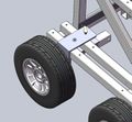
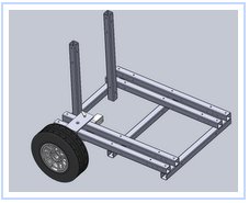
See pictures of wheeel without Quick Connect (from Solidworks):
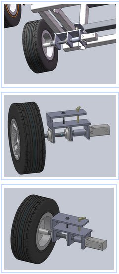
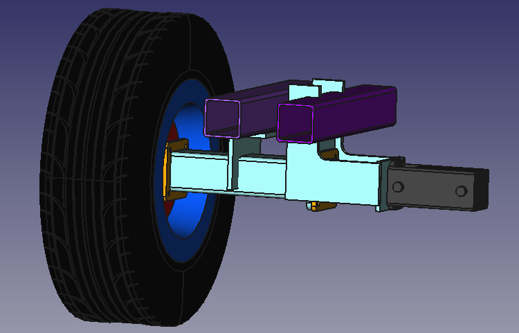
See pictures of wheel With Quick Connect:
and the real object:
.
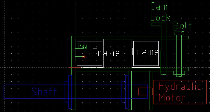
Concept Quick Release Wheel
Design Rationale:
- Triple mechanism of holding using peg, a cam lock, and a bolt:
Download File:Wheelmount.dxf
See it:
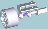
Model:
Download pngs of above and STEP file - File:Wheelmodel.zip
STEP file viewed with VariCAD Viewer -
Relation to frame:
Download the relation to frame, STEP and X_T files - File:Wheelmodel2.zip
Reducing loads on the shafts and bearings
In order to reduce the bending load of the shaft the following design could be implemented:
The idea is moving the main bearing as close to the wheel center as possible. This will reduce the bending moment on the shaft close to zero and reduce the loads on the bearings. The load on the roller element bearing close to the wheel will approximately be halved and the roller element bearing close to the motor could actually be replaced now by a much smaller one.
In this design the 4"x4" transverse tube takes over the whole bending moment for transferring the forces from the wheel to the frame. There are different possibilities for anchoring this tube to the frame. One should only keep in mind that the loads will push the external frame tube upwards and pull the internal one downwards.
You can download the CAD model of this first rough design in the following file
Download FreeCAD model: File:Wheelmodel 3.FCStd
Discussion
What is the critical clamp-down/disconnect mechanism?
What is the impact of reducing bearing loads on lifetime of bearings?
Lifetime is very load sensitive (more than cube of load):
- Doubling load reduces life to one tenth. Reducing load by one half increases life by ten,
- Doubling speed reduces life by one half. Reducing speed by one half doubles life.
See [1].
Are there similar industry standard designs?
Solution Pathways for Addressing Failing Motor Couplers
Solution Pathway 1
Concept:
- Use a motor with more torque
- Direct coupling to wheel eliminates bearings, shafts, and collars - sorry, this won't work, still need bearings and shaft <the motor already has shaft and bearings, are you assuming they aren't strong enough or have you done design analysis to be sure?
- Retain tracks
- Use one motor per side to eliminate motors 'fighting each other' <This is not practical if the motor is attached directly to the wheel if there are two wheels on each side.
Possible solution: 15,000 Inch Pound Motor
Solution Pathway 2
- Use 2 motors per side, and same drive train as in LifeTrac Wheel Assembly Video, but with splined shaft motors;
- Use tracks
- Use Cushion Valve to prevent localized pressure spikes
- Do motors 'fight each other' in this case?
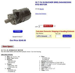
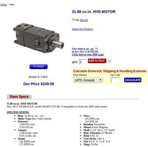
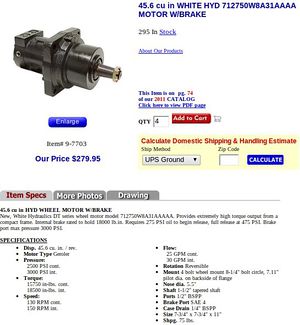
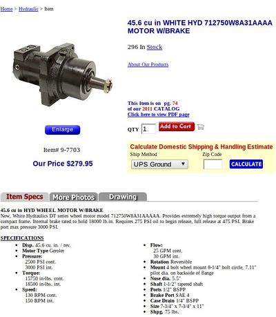
- The new splined motors are these from Surpluscenter:
Pathway 3
- Use 2 motors per side, and same drive train as in LifeTrac Wheel Assembly Video, but with Splined Shaft Motors
- Use no tracks, but 50/50 Flow Divider
- Use double relief valve (Cushion Valve) to prevent localized pressure spikes
- Do motors 'fight each other' in this case? They may, but they won't break due to double relief valve.
- The new splined motors are these from Surpluscenter:
Pathway 4
- Same as Pathway 3 but with [[2]]
Pathway 5
- Same as Pathway 4 but with [3] for traction of 4200 lb, comparable to a F250 pickup truck, matching maximum available traction from 16" truck tires
Parts Sourcing
- Bearings; https://www.surpluscenter.com/item.asp?item=1-210-30-4-C&catname= minus the collar, which I take off and use:
- the double split lock collars - https://www.surpluscenter.com/item.asp?item=1-2768-187&catname=powerTrans
- Motor: http://opensourceecology.org/wiki/15,000_Inch_Pound_Motor
- Hub: http://www.surpluscenter.com/item.asp?catname=hydraulic&item=9-9003
- 1-7/8" cold rolled steel shaft
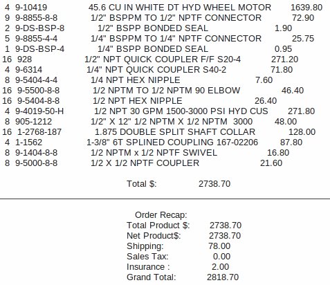
- From Surpluscenter:
- [4] 9-10419 45.6 CU IN WHITE DT HYD WHEEL MOTOR 1639.80
- [8] 9-8855-8-8 1/2" BSPPM TO 1/2" NPTF CONNECTOR 72.90
- [4] 9-8855-4-4 1/4" BSPPM TO 1/4" NPTF CONNECTOR 25.75
- [16] 928 1/2" NPT QUICK COUPLER F/F S20-4 271.20
- [4] 9-6314 1/4" NPT QUICK COUPLER S40-2 71.80
- [8] 9-5404-4-4 1/4 NPT HEX NIPPLE 7.60
- [16] 9-5500-8-8 1/2 NPTM TO 1/2 NPTM 90 ELBOW 46.40
- [16] 9-5404-8-8 1/2 NPT HEX NIPPLE 26.40
- [4] 9-4019-50-H 1/2 NPT 30 GPM 1500-3000 PSI HYD CUS 271.80
- [8] 905-1212 1/2" X 12" 1/2 NPTM X 1/2 NPTM 3000 48.00
- [16] 1-2768-187 1.875 DOUBLE SPLIT SHAFT COLLAR 128.00
- <strikethrough bc old design>4 1-1562 1-3/8" 6T SPLINED COUPLING 167-02206 87.80
- [8] 9-1404-8-8 1/2 NPTM x 1/2 NPTF SWIVEL 16.80
- [8] 9-5000-8-8 1/2 X 1/2 NPTF COUPLER 21.60
Total $: 2738.70
Cut List for Wheel Upgrade
For each wheel (note dimensions are slightly off in above drawing)
- [1] 1-7/8" shaft - 28" long
- [1] front plate - 1/2"x8"x14" flat (if reusing old plate, just weld 2" on top) (not needed if modifying existing)
- [1] mid plate - 1/2"x8"x9.5" flat (not needed if modifying existing)
- [1] back plate - 1/2"x8"x9.5" flat
- [1] top horizontal plate - 1/2"x8"x15.5" flat
- [1] bottom horizontal plate - 1/2"x8"x21" flat ->-> extend by 1/2" to add collars, shorten sprocket coupler by 1/2" (see cut list for qc wheel upgrades at FeF)
- [1] bottom reinforcement plate - 1/2"x2"x21" flat -> extend by 1/2"
- [1] side reinforcement plate - 1/2"x4"x21" flat extend by 1/2"
- [1] DOM (1/4" wall) - 1"x1-1/2" - 4" long
- [1] DOM (1/4" wall) - 1-7/8"x2-3/8" - 4" long
- [1] Cam handle weld plate - 1/2"x2"x4" flat
- [1] Cam handle 1" rebar - 6" long
- [1] Cam handle 1" rebar - 12" long
Total for 1 Wheel
- 1-7/8" shaft - 28" long
- 1/2"x8" flat - 69.5"
- 1/2"x2" flat - 25"
- 1/2"x4" flat - 21"
- DOM (1/4" wall) - 1"x1-1/2" - 4"
- DOM (1/4" wall) - 1-7/8"x2-3/8" - 4"
- 1" rebar - 18"
Total for 4 Wheels
- 1-7/8" shaft - 9'4" long
- 1/2"x8" flat - 23'2"
- 1/2"x2" flat - 8'4"
- 1/2"x4" flat - 7'
- DOM (1/4" wall) - 1"x1-1/2" - 16"
- DOM (1/4" wall) - 1-7/8"x2-3/8" - 16"
- 1" rebar - 6'
Axial Load Test Data
Updated 4/11/2012
We have performed 20 hours of field testing for axial load capacity in skid-steering operation. This included carrying of 2000 lb pallets of bricks and moving 2400 lb battery banks with the front loader. We have observed successful negotiation of inward axial forces on wheel shafts, and we have observed outward slippage of shafts by 3/8".
This is caused by insufficient holding force via 2 double-split collars as the sole retention mechanism for inward axial thrust. The results indicate further that the 4 double split-collars that prevent inward slippage of the shafts were sufficient to prevent any inward shaft motion -as no inward slippage was observed on any wheel.
To address the problem, we are adding 2 additional double-split collars to the quick connect wheel system - on the inner side of the inner bearing plate. To do this, we are moving the inner bearing plate 1/2" out, and the motor mount plate 1/2" in, and shortening the coupler length by 1/2". This will allow the necessary clearance of 1-3/4" for 2 collars + 2 washers. This was not done before because space considerations did not allow 2 more collars and washers to fit. We are making additional room now. The motor mount plate cannot be moved further back because opposing hydraulic motors do not have sufficient space between them.
Peer Review
This page should be peer reviewed by hydraulics specialists, mechanical engineers, CAE experts, machine designers, farmers, permaculturalists, and others.
Field Testing, Failure, Repair
Calculations
Tire Size and Dimension Calculator
