Steam Engine Build/Piston Connector Rod
Jump to navigation
Jump to search
Main > Energy > Steam Engine
Steam Engine Build Instructions
Description
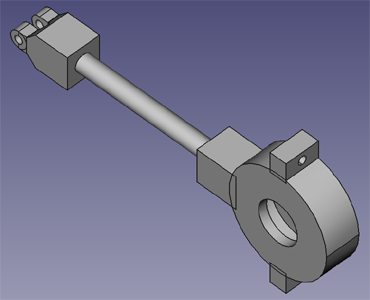
The connector rod connects the piston stem to the crank on the crankshaft. One end is fixed to the piston stem and travels in a reciprocal, linear motion. The other end is attached to a crank on the crankshaft and travels in a circular motion. The crankshaft end contains a bearing case and ball bearings to reduce wear on the crankshaft.
The connector rod is built up from three elements:
- Coupler
- Bearing Case
- Rod
CAD
Drawing
Instructions
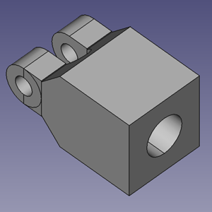
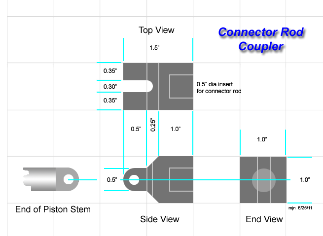
Coupler
Using a piece of high quality steel:
- Cut a 1.5" length from 1.0" square bar stock
- Drill a 0.5" dia hole in one end to a depth of 0.75"
- From the top face, drill a 0.25" hole at 0.5" from the left end.
- Cut a slot 0.25" wide to meet the hole just drilled.
- Bevel the piece at a 45 degree angle as shown
- Drill a 0.25" hole 0.25" from the end into the side face
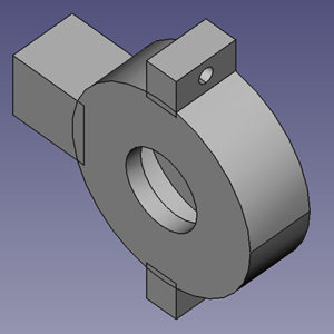
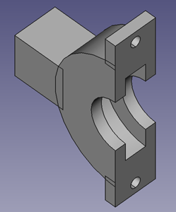
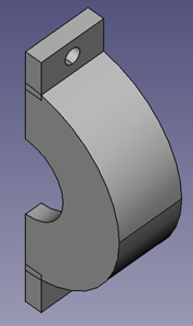
Bearing Case
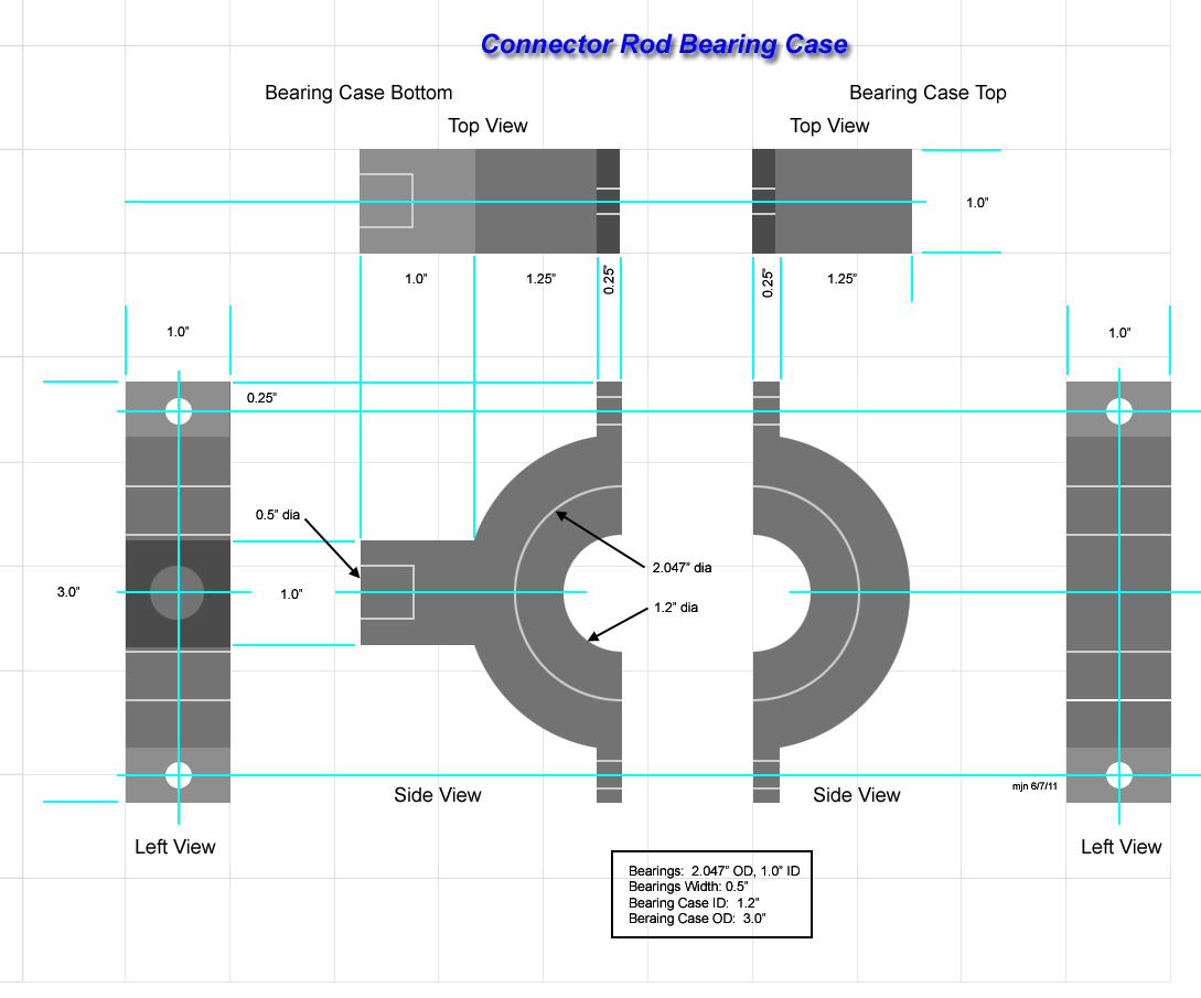
The bearing case can either be milled from high quality steel, or the circular portion turned on a lathe and bolt tabs welded on.
- Drill bolt holes 0.25" dia.
- Inside bore is 1.2" dia to hold a bearing unit with a 1.0" bore (shaft size)
- A cylindrical channel is cut inside 0.5" wide and 0.647" deep
Assembly
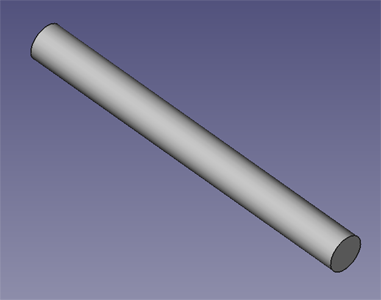
- Cut a length of 0.5" rod 5.0" long
- Insert the rod into the coupler and weld it
- Insert the rod into the bearing case and weld it.
