Steam Engine Design/Crankshaft
Main > Energy > Steam Engine
Description
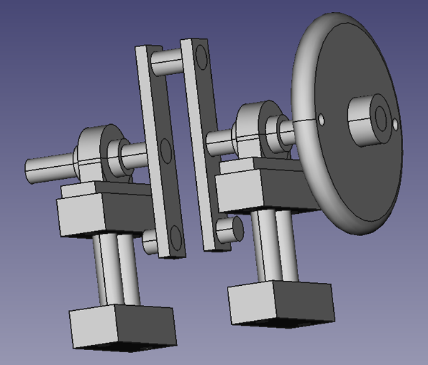
This is the proposed design for a crankshaft design using a simple return arm.
Features
- Crank arms are balanced by equal weight of metal on both sides of the centerline of the shaft.
- Crank pin is balanced by taking an equal length of metal, splitting it into two, and welding the pieces on the opposite side of the crank arm.
- Pillow blocks with internal bearings
With careful welding, this crankshaft should come close to being balanced, though the piston rod may upset the overall balance. Balance can be further adjusted by removing or adding metal to the offset weights.
CAD
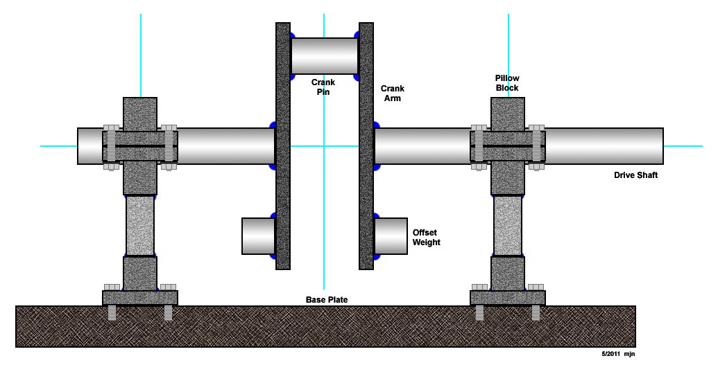
Diagram
The crank pin offset is 2", which corresponds to the half the piston cycle length.
The bearing case on the piston connector rod is 3" wide, which adds 1.5" to the offset.
Add another 1" for clearance gives a total of 4.5" distance between the crankshaft center line and the top of the base plate.
Fabrication Notes
Welds are shown in blue in the diagram above. Initial prototype of the crankshaft should be welded rather than complicating the design with an assembly that can be taken apart. Later, a more modular design might be necessary to accommodate multiple steam engine cylinders.
The crank pin and offset weights will need to be carefully cut. Using a cutting torch is not accurate enough since crank pin and offset weights must be of equal weight. A thin cutting wheel would probably do it.
Fabrication Procedure
- Cut shaft to size
- Weld crank to shaft
- Face off crank arms on a lathe
- Drill out 2 crank arms one on top of the other
- Bolt crank pin in place
- Use bearing on crank shaft end
The above addresses perfect alignment of main shaft and crank pin. Welds can be added on the opposite end for perfecting the counterbalance.

