Steam Engine Design/White Cliffs Report
Main > Energy > Steam Engine
These notes are made on "The White Cliffs Project - Overview for the period 1979-89" [1] by S. Kaneff, Australia National University.
General
A 25kW projec was intially proposed.
Australian National University formed a company to build WC - ANUTECH Pty Ltd
Energy Authority Reps: Peter Holligan and Malcom Wiliams
ASD 1.8 Million
Spinoffs:
- collector technology for industrial process heat
- engine techology
- biomass fueled and waste heat utilization
- cogeneration
Power Kinetics, Inc. of Troy, NY holds the exclusive license for N and S America.
Contributors
- R.E. Whelan
- E.K. Inall
- H.P. Cantor
- K. Thomas
- P.O. Carden
- G.J. Vagg (Steam Engine design)
- K.G. Fulton
- Environ Mechanical Services of Sydney
- Peter Thomson of White Cliffs
Other Papers:
- "Feasibility Report and Project Assessment" by Environ Mechanical Services Pty, Ltd. Oct. 1979
- "Considerations of Heat Transfer System Stage 1" by Davy McKee Pacific (Melbourne), comm. by ANUTECH Pty, Ltd. Jan. 1098.
- "Report on white Cliffs Solar Power Station Steam System" by Merz and McLellan and Partners (North Sydney), comm. by ANUTECH Pty, Ltd, Aug. 1980.
- "Review of the Status and Viability fo the White Cliffs Project" by Alan Frost, comm. by Engergy Authority NSW. Mar. 1982.
- "Review on the White Cliffs Experimental Solar Power Station" by Prof. J.R. Glastonbury, U. Sydney, comm. by EA NSW, Oct. 1985.
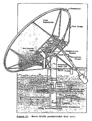
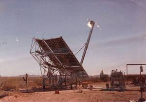
14 parabolic collectors to produce 25 kWe.
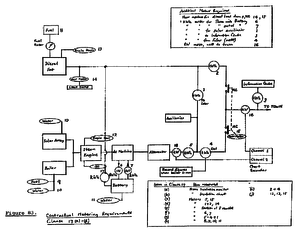
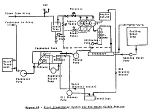
See WC-Functional-Diagram.png
Feedwater at pressures up to 7 MPa (70 atmospheres) pumped in parallel through the absorbers of 14 parabaloid dishes.
Tracking in azimuth and elevation through two rotary joints in each collector.
When steam exceeded 180 degrees C, a bypass valve closes causes pressure to build. When pressure reaches 2.7 MPa, a throttle valve opens and the engine starts. An electric starter motor ensures correct rotation of the engine. Engine speed increases as it warms up. When 1500 rpm is reached (synchronous speed for 50Hz), further speed is applied to an AC/DC rotating machine set through a free wheel devices (this is a kind of govenor? - mjn)
Excess energy is stored in batteries.
A thermodynamic steam trap is used to prevent water from entering the engine - only steam.
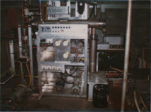
Exhaust steam is condensed and recirculated. Oil is removed from the condensate by filter and centrifuge and by a vortex chamber.
Removal of lubricating oil from the exhaust steam and condensate was a challenging part of the project.
To reach 23% heat to mechanical efficiency, steam quality can reach up to 500degC adn 7 MPa.
Oil is injected into the cynlinders t o assist lubriation.
The report indicates that building the steam engine was the major part of the project. The solar collectors posed minor problems.
Other single dish/engine projects:
- Advanco Dish/Sterling system at Indian Wells, CA
- McDonnell Douglas Dish/Sterling mdoules (see Colemand and Raetz, 1986)
A Bill of Materials is presented on pg. 255.
Design
Design Objectives:
- Allow all available solar energy to be collected and used
- Design all components for maximum transmission and minimum loss
- Simplicity - including improved reliability, reduced operating and maintenance demands
- Use available standard components, purchased components included:
- Operating valves
- non return valves
- tubing and fittings
- heat insulating materials
- AC and DC machines
- Contactors
- Control and protection gear
- Electromechanical and electronic relays
- Mechanical couplings including free wheel unit
- Storage batteries
- Condenser and cooling plant
- Pumps and drive motors
- Controllers
- Steam trap
- Water treatment plant
- Bearings
- O-Rings
- Filter elements
- Gear boxes and electric drive motors
- Engine Block
- Crankshaft
- Connecting Rods
- Oil pump
- Governor gear
- Starter
- Pistons
- Things that had to be built included:
- Almost all components of the parabolic dishes
- Absorbers
- Rotary steam/water joints
- Engine conversion parts
- Oil/water treatment components
- Feedwater tank
- Skimmer
- Oil separation column
- Throttle and drain valves
- Centrifuge
- Steam safety valves
- Electronic control units for the dishes
- Central station control system
- Torque balance
- Automatic protection system
- System components must be transportable to remote sites
- Environment compatibility including:
- Selection of materials
- Environmentally tolerant components
- Structures to withstand wind, rain, temps, and other stresses
- Automatic parking of the array in high winds
- High standards of robustness and reliability
- All features of a large system including configuration, design, installation, control, operation, and maintenance
- Modularity
- Automatic, unattended operation
- Continuous, standalone operation
Design Considerations:
- Array fluid flow paths - optimized flow distances to avoid losses
- Rated Steam / Feedwater Conditions - use stainless steel pipes and fittings
- Insulation, Losses, and Superheat - retain all possible heat gained
- Design Design - cope with wind, back silvered glass reflectors
- Storage - use batteries
- Heat to Mechanical work conversions - reciprocating expander engine
- Cooling water - lots of cool water needed for condensing systems - used a rainwater collection system for feedwater
Descriptions of insolation, wind, rain, dust, temps, etc. at White Cliffs. Similar measurements of OSE sites should be considered.
Graphs show the effects of cloud cover on insolation.
Configuration, Components, and Systems start on page 59.
Steam engine was based on a design by Cmdr. G. Vagg.
Major Sub-systems
Major subsystems include:
- Energy Collection - Solar Array
- Energy Transport - Field Ducting
- Energy Conversion - Steam System
- Energy Utilization - Electrical System and Load
- Energy Storage - AC/DC Better System
- Operating System - Automatic Controls and Data Acquisition
- Environmental Monitoring - Insolation and Wind
Dish Design
Dish Design Considerations (see list pg. 65/66)
Lots of information on dish design. Details on absorbtion cavity.
Field Ducting description starts on page 110.
See details of solar collector construction on pg. 167.
Steam System
Steam System starts on page 122. Steam Engine on page 129.
A vacuum pump is used facilitate steam expansion
Water cooled condensing
The engine has automatic motor-driven valves for:
- bypassing steam to tohe condenser when steam quality is not adequate (ie, before start)
- admitting or shutting off steam (throttling)
- allowing drainnig of cylinders of water just at start up
Water/Oil Separation
- A vortex column that retains oil droplets and condensed steam
- A skimmer in the feedwater tank to remove surface oil
- A centrifuge for separating oil and water
- Filter pump and fine filter to remove oil in emulsion with water
- Later, two stainless steel disks rotating on horizontal axis in feedwater tank
Water used should be pH neutral to avoid corrosion problems.
Safety
- Pressure relief valves (PRV) on incoming steam line to engine and on the condenser
- Alarms that will shutdown the system:
- Engine oil pressure
- Oil tank level (high and low)
- Feedwater flow
- Condenser cooling water flow
- Vacuum system
- Centrifuge
- Oil water pump
- Liquid level in the vortex chamber
- Engine over speed (w/ governor backup)
- Excess wind
Steam Engine
pg. 129
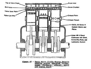
A converted Lister Diesel Engine using piston operated ball valves.
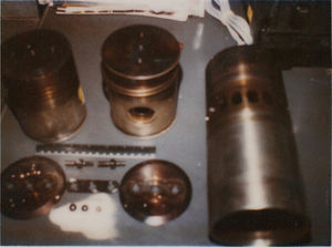
Cylinder (liner?) and pistons may be removed.
Piston Operated Valves (POV)
Steam is applied to a chamber in the head of each cylinder.
Engine is started by an electric motor.
As a piston approaches top dad center, the pins in it's crown lift the three ball valves from their seats and steam enters the cylinder until the valves seat again past dead center.
Steam expands while applying pressure to the piston until the piston exposes the normal exhaust ports int he cylinder liner which was made for a 2-stroke diesel engine.
Cylinders, cylinder heads, valve seats, and steam chambers (these are the conversion components) can be made from cast iron, mild steel, and stainless steel (no notes on which material was used for what).
Water can collect in the steam line to the engine which can enter the engine on start up. If there is water in the cylinders, the starter motor can't crank the engine. A motor-operated drain valve was fitted with a port to each cylinder. Interlocks prevent the stater functioning until the drain valve is open. If water isn't allowed to build up in the input lines, this is not necessary. As soon as the engine starts, the drain valve is closed via signal from engine speed. While running, water in the steam is diverted via a steam trap into exhaust lines.
The valve mechanism was a major area of development. Extended, reliable operation was only achieved after much attention was given to the geometry and dimensions of the valves. Material and hardness selection was important.
Energy Storage
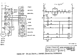
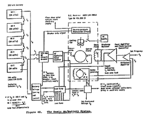
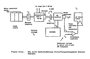
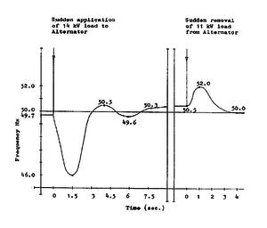
AC and DC machines are mechanically coupled to the engine via a freewheel (flywheel) coupling. Digression from 50Hz causes the DC machine field to adjust operation to restore frequency.
When there is no solar steam, the steam engine stops (or may be supplied from an auxiliary boiler). When engine is stationary, the AC/DC set continues to supply an electrical load from betters until 80% discharged (about 1.8 volts per cell). When batteries can no longer maintain the load, a backup diesel engine is brought into service automatically.
Loss/Efficiency
- Because of conversion loss, AC load energy from the DC machine/battery is about 52% of steam engine output.
- AC load energy available is about 57% of direct output from the alternator with same engine output.
Storage Cells (lead acid)
- Lucas-type LNN 23/25 heavy-duty traction cells
- Lucas-type LNN 29/31 cells
Boiler and Super Heater
pg. 152
The steam system can be operated from either solar generated steam or fuel fired boiler. Conversion of fuel energy to fluid local heat is 85% efficient.
Boiler is constructed from three monotube energy absorbing sections comprising a preheater (tube coil), main heater (tube coil), and a super heater (pancake wniding between the two coils). 19mm OD, 1.6 mm wall thickness stainless steel tubs with welded connections in the heat zone. Insulated by a 50mm durablanket (calcium silicate) in a stainless steel cover. A small 6mm tube can be used to bleed off steem from the main line to clean the monotubes, thus preventing buildup of material on the outside of the tubes.
Unable to get the super heater to produce dry steam.
Measurements
pg. 156
Instruments to monitor:
- Insolation
- Wind Speed
- Wind Direction
- Temperature
- Pressure (water and steam)
- Feedwater Flow Rate
- Material Properties (mirror reflectance)
- Power
- Solar Power to Town
Hardware Experiences
pg. 187
After initial problems were solved, the system ran for six years with relatively few problems. No design changes. Reliability has been excellent. Power demands have been met.
Couplers
Hardware problems largely due to poor quality commercial components - pumps and relays especially. Coupling from the engine to the AD/DC set failed after five years (a Morse unit), likely due to inadequate lubrication. Replace with a Borg-Warner unit.
Engine Oil
Pg. 189
Too high or too low an oil level will cause problems in the steam engine. An oil level switch/alarm was installed. A scavenger pump was added to pump oil from the sump to the oil tank. This also cools the oil somewhat.
Piston Operated Valves
pg 190
"Once we had grasped all of the affective parameters and understood their inter-relationships, we were able to produce very effective operation which we are now optimising,preparatory to developing and building bigger engines, including engines which employ ceramic valve (and piston) components."
The valve mechanism was difficult to perfect.
The pistons were modified to allow pins to be inserted in them. The original GM cast iron pistons were modified to include a mild steel cap (after removing the top of the cast iron piston). There was trouble with weld failure. Cast aluminum pistons with steel tops were tried, but failed.
The final valve assembly has operated for more than 1000 hours with out failure. Ceramic valves and pistons would be cheaper to produce and allow higher operating temps and pressures.
Oil Separation
Chlorothene was added at one point to remove oil suspended in water. It worked wonderfully in removing oil from water, but caused corrosion and pin-hole leaks in several parts of the system. Use was discontinued.
Performance
Steam Engine Performance
pg 213
Use of commercial components was useful to enable cost effectiveness and maintenance.
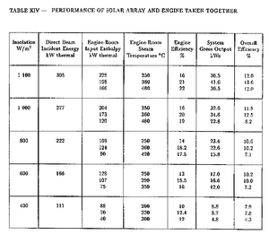
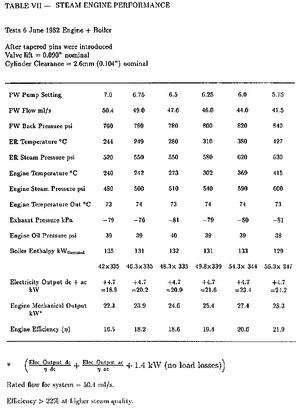
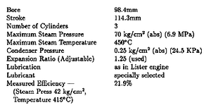
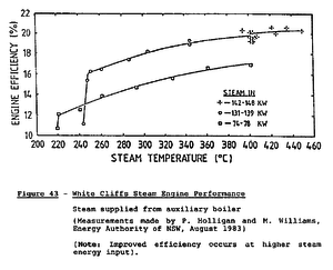
The steam engine, with vacuum assisted exhaust/condensation achieved efficiencies of over 20%. This was achieved in part through high quality heat and steam. Use of a vacuum pump assisted in extracting maximum work from the expanding steam (vacuum is presumably on the exhaust plenum).
"Because of the restrictions imposed by license agreements, details of the engine which result in it's high performance are not included."
The steam engine requires two hours of operation before attaining optimal conditions.
Engine runs at a constant speed of 1500 rpm.
The vacuum assisted exhaust improved engine performance determined by mass flow, cooling water terms, and input steam quality. Vacuum had 25degC cooling water, of -80 kPA, inlet steam temp of 415degC, pressure of 600 psi, exhaust temp of 73degC, input steam enthalpy of 129 kW thermal, mass flow of 41.5 g/s, shaft output of 28 kWmech.
An identical engine with appropriate valve settings operates at 1800 rpm, output of 49 kWmech, with a vacuum of -70kPa, 420degC steam inlet, and 73degC exhaust temps.
Arrays and Steam Engine
pg. 235
Starting and stopping the system is described on pg.238.
Achievements
Start on page 267.
Claimed achievements include:
- Station supplies power to White Cliffs reliably.
- Works on a continuous, stand alone basis.
- Technology is suitable for the application.
- Objectives of the project were met.
- Cheapest on a per unit basis.
- Development achieved largely in one step.
- Future cost potential is good.
- Concepts and principles selected very successful - no change.
- Some original development with signficance for future work.
- Most number of operating hours of any solar thermal system.
- Appropriate for unsophisticated production and running.
- Value of going out to field at an early stage.
- Increased awareness of environmental effects.
- Array of modular collectors can operate successfully.
- Dish sizes must be increased.
- Very successful steam engine with extensive applications.
- Project gained international visibility.
- Can be applied to other settlements without power.
- Several spinoffs.
Lesson Learned
Some learning:
- It is practical, cost effective, and competitive to supply via solar power.
- Great scope and potential for more economical solutions.
- Praticability, reliability, and cost effectiveness can be gotten without exotic systems.
- Effective starting point for further development.
- Assessment of system was hampered by light town load.
- Comprehensive management let to success.
Impact of Technology
Impacts:
- Licensing to a US firm.
- USA design of a site on Molokai.
- Development of a new generation large dish/engine system.
- Development of rural village power supply at White Cliffs.
- Influencing the US Dept. of Energy to establish dish/steam systems.
- Development of a range of components for solar thermal systems.
Heat Engine Research and Development
Research:
- Putting enhanced steam engine on a more theoretical footing.
- Program to investigate various classi converters.
- Investigate concepts to utilize low voltage outputs.
- Generalize and extend energy conversion theory.
- Determing the practical limits to efficiency and outputs.
Solar Collection and Concentration
Conceptual Advances:
- Determine optimal size of collectors.
- Determine optimal shapes of collectors.
- Cavity receivers.
- Effective measures to reduce trauma on absorbers
- Investigation of indirect irradiation of absorbers
- Developments using direct absorbers
