Steam Engine Research/Lubrication
Main > Energy > Steam Engine
From, Steam Engineering, A Text Book by William King
109. Lubrication
In the operation of the steam engine there is power lost in overcoming the friction between sliding surfaces and it is the object of lubrication to reduce this loss to a minimum. If bearing surfaces were permitted to rub each other without lubrication they would soon become damaged from heating and would render the engine inoperative. the lubricant most commonly used is mineral oil, and it's introduction between the surfaces in moving contact, in the shape of a think film, greatly reduces the friction and permits a save and easy movement. Some form of sight-feed drip cup, filled and operated by hand, is extensively used in lubricating the bearing surfaces of the engines, though a preferable method is that of having a system of pipes lead to the bearings from a central tank, the oil being fed either by gravity or by pressure.
The lubrication of the moving parts of an engine that are in contact with the steam, such as valve and piston, is effected mechanically, or hydro-statically through the medium of the steam. When mechanical means are employed, such as a hand force pump, oil is in injected the steam pipe closest to the valve chest, or into the valve chest itself, and there is atomized and carried by the steam to the wearing surfaces. The steam sight-feed oiling devices are operated by the hydrostatic pressure of a head of water form in the devices by steam condensation, and by the displacing power of water over oil.
111. Grease Cup
A heavy grease product of mineral oil is often used for lubrication. In some instances the grease flows from the cup by gravity as it is melted by the heat of the bearing, but more frequently the grease is forced between the bearing and surfaces by the compression of a spring.
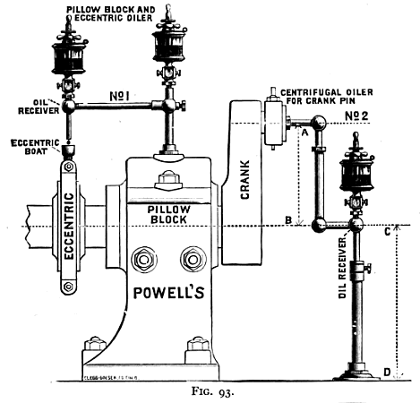
Fig. 93 - Pillow Block and Eccentric Oiler
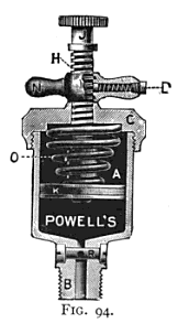
Fig. 94 show a compression grease cup in section. The filling of the cup and its action is as follows: By turning the jamb nut N to the right, the spring O is compressed and the plunger K drawn to the top, exposing the full length of the stem H. Then unscrew the cap C and fill the chamber A with grease, leaving space at the top to receive the plunger K. Replace cap C and apply pressure by releasing the jam nut N, running it to the top of the stem against button J. The quantity of grease fed is controlled by the cut-off R in the shank B. To stop the feed at any time, run jamb nut N down to the cap C, thus taking the tension off the spring. The jam nut is provided with a spring stop D which engages the flat on stem H and is of sufficient tension to hold it at any desired point.
Fig. 94 - Compression Grease Cup
--Mjn 19:05, 22 May 2011 (PDT)

