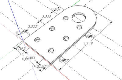
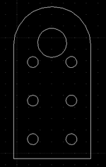
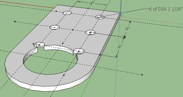
Stock Pivot Plate
FreeCAD files
LifeTrac 6 Pivot Plates
Change Log:
- Rounded part of pivot plate was shortened to prevent interference
- All holes were increased by 1/16" to 1-1/8" to facilitate bolting
6 in 60 Pivot Plates
'Needs the Stock Pivot Plate Sketchup with 3" hole, which is the hole after the precision tubing has been welded in. Further, 6 in 60 Buildout testing has shown that the stock pivot plates need to be 1/4" shorter at the rounded part because of conflicts when 2 of these plates are put together from opposite sides in joints. To address this, please generate a stock plate where the half circle begins 1/4" further away from the rounded edge, so that the overall plate is not 16" long, but 15-3/4" long. Leave the curvature identical, just move it 1/4" inch away from edge.
Full Size Design Files, Sketchup
- 1. Realistic Design File: Needs 3" hole for exactly how 3" shaft will fit. Lengh of 15.75" as disussed above. - SKP: File:Pivplate1575-3.skp
Scale Model 3D Printing Files
- 2. Design File for 3D printing - Same as Realistic Design File except at 1/8 scale, so plate is 1" wide and ~2" long in this case. - File:Pivplatescaled-3.skp
- 3. STL File for 3D printing - same as above, exported to STL - File:Pivplatescaled-3.stl
- 4. Fixed STL File for 3D Print - see STL File Fixing for how to process an STL file to prepare it for printing - File:Pivplatescaled-3f.stl
- 5. Configuration File for 3D Print - Each type of printer uses a configuration file to accommodate differences between printers. Use this file for printing the part - File:Pivotscaled-3f-config.config
- 6. Optimized Design File for 3D Printing - For a specific printer to print a 3D print more effectively, the 3D printing file may want to be modified for faster printing. For example, the wall thickness could be changed so that the printer deposits a single-strand wall thickness for significantly increased printing speed. This will have to be determined by printing the file from points 6-7 and seeing the results. Wall thickness must be balanced with structural integrity/printability of the resulting parts. Further, sacrificial bridges between parts may need to be added so that tall structures being printed do not shake around on the moving printing bed.
- 7. Optimized STL File for 3D Printing - File:Pivplatescaled-3-opt.stl
- 8. Optimized Fixed STL File for 3D Printing - File:Pivplatescaled-3f-opt.stl
- 9. Configuration file for Optimized 3D Printing - File:Pivplatescaled-3f-config-opt.stl
Laser Cutting
For Laser Cutting out of stiff construction paper at 1/8 scale - we need to start with a scale model in Sketchup, corresponding to Design File for 3D Printing. Take the component to be printed. In order to generate a flat structure, the DXF can be generated directly from this SKP file.
- 10. Laser Cutting File - DXF generated from SKP Design File for 3D Printing: File:Pivplatescaled-3-laser.dxf
For non-flat files - such as tubing - this requires more work. Start with the tubing file in sketchup, export to DXF for the one side - and basically draw the rest of the tube as a flat structure - so a rectangle with perforations for the 4 folds that will allow a flat cutout to be folded into a 4-sided tube. Once folded, the tube should be taped together, or a tab should be added so taping together is easy.
Full Size Files for CNC Cutting (Acetylene Torch, Laser, Plasma)
- 11. SKP Design File for Generating CNC Torch/Plasma Cutting Files: Same as above except the hole accommodates a piece of precision tubing with 0.5" wall - so it is 4-3/16" diameter to allow 3/32" welding gap. This kind of spacing has been tested with laser cut metal. - File:Pivplate1575-4.skp
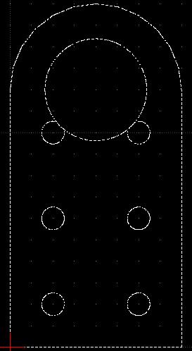
- 12. DXF CNC Cutting File - same as above, but exported to DXF. - File:Pivplate1575-4.dxf
Older Version
DXF file - File:Stockpivot.dxf
Note: the correct large hole diameter in the above is 4.75", which gives 1/8" room around the DOM for effective welding.
Note: the above is used to generate a CAM file for CNC Torch Table cutting and Laser Cutter modeling - for the pivot plate. In practice, a 4.5" OD DOM with 3" ID is welded inside the 4.75"-4.875" hole (Mickey Mouse hole) to generate a pivot plate for a 3" shaft. To generate a CAM file for 3D printing, one must consider the 3" tubing and print out a 3" hole, not a 4.75"-4.875" hole. 4.75" is recommended as a hole for CNC cutting (leaves exactly 1/8" space around DOM for welding) - and a 4.875" hole is recommended for manual cutting to address inaccuracies.
- File:Stock Pivot Plate.skp
- File:Stock Bonding Plate 8 inches x 16 inches.skp
- File:Stock Spacer Plate 8 inches x 8 inches.skp
Links
- Samthetechie Log
- Print how-to - Ultimaker Post on Using Sketchup for 3D Printing.
Comments
- To me, the last holes and big hole are too close.
You are right for most cases. There is a rare occasion when those small holes are used to bolt together multiple pivot plates while allowing a large shaft to be inserted, which may be useful under special circumstances. We can leave these for now, but will get more test data from our machines to see when these are useful. If they prove useless, we'll take them out or move the large hole farther out.


