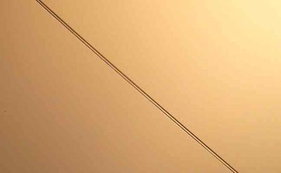
TightWire Alignment
Tight wire alignment is a technique for measuring straightness of large equipment components. (example supplier) It has a long history although it has been largely displaced by optical methods. It may be appropriate for creating straight movement axes in lathes, torch tables, and other machine tools (especially appropriate for concrete-bed, grouted-ways designs in a start-from-scratch model).
Principle
A wire stretched between two points establishes a nearly straight line. Gravity causes a sag which can be predicted accurately if the tension (e.g. from a hanging weight) and wire material are known. The distance from the wire to an object of interest (e.g. a guideway, bearing housing, travelling slide, etc) is usually measured manually with a micrometer device which "beeps" on electrical contact with the wire.
Optical sensor
As an alternative to manual micrometers, a close-up camera may observe the wire position. Kevan Hashimi at Open Source Instruments describes such an instrument for scientific work. Here we describe a low-cost adaptation to the machine-alignment task. The procedure for aligning ways is
- If no carriage exists yet, fabricate a kinematic slider to ride on the ways
- Place brackets (if necessary) and string a tight wire parallel to the ways.
- One wire support is a pulley wheel; hang a dead-weight for tension.
- Mount the mirror assembly (described below) to the carriage or slider, centered on the tight wire.
- Attach a video camera to the carriage, looking into the mirrors. Close focus ("macro") is useful.
- Run the carriage up the ways, recording video
- run processing program on the video, which will report deviations along the travel (sensitivity better than 0.0005 inch should be achievable)
- adjust ways with shims, repeat tightwire measurement.
- apply grout and allow to harden, holding ways in permanent alignment.
This sensor relies on a single camera looking at images of the tight wire in two small mirrors. The assumption is that some kind of electronic camera (webcam, cell phone, etc) will be available on an ad hoc basis, but is not permanently dedicated to the instrument.
Proof of concept
Note: This is just a proof on concept "mock up", I don't think this design is stable enough to be usable yet.
For testing I used an LG Optimus cell phone camera. This camera can capture stills and moving video.
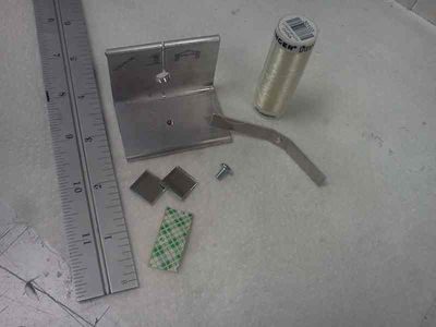
Parts of the optical sensor:
I used nylon "invisible thread" 0.005-inch diameter. Steel would probably be better (more opaque, for starters).
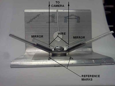
Assembled
The mirrors are placed so that the images of the wire (when centered) are colinear with the reference marks. By doing the video measurements relative to the reference marks we make the exact location of the camera non-critical.
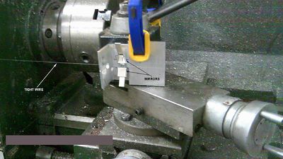
Set up for checking lathe way straightness
The company where I work has a lathe, so I set up this trial on it.
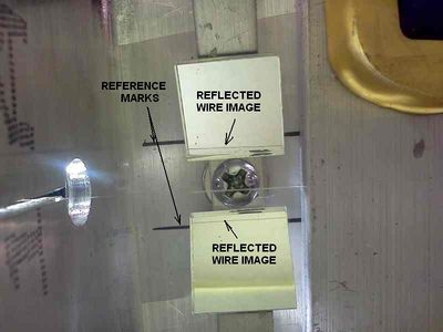
Sample camera frame:
Clearly some repositioning of the mirrors would help. Ideally we could get a reflected image comparable to this (which was taken with the same cellphone camera, but with no mirrors and a more careful setup):
The necessary image processing program has not been written. It could possibly be written as a macro in ImageJ, a great open-source image/vision program.
Features needed:
- Extract centerlines of wire images (one in each mirror)
- Extract centerlines of reference lines
- Establish displacement of wire image from reference line
- Establish scale factor from spacing between the two reference lines
- Adjust for angle between the two reflected sightlines (it won't be exactly 90 degrees)
- Adjust for wire sag (need to know tension weight and density of wire material)
- Report table of x- and y- deviations from centerline along travel distance.
- Report deviations from straightness (i.e. deviation from best-fit straight line)
