Universal Power Supply/Proposal 1
Overview
Proposal 1 is outlined in File:UPS CAN proposal blockdiagram.pdf. The concept is to use a controller card that continuously monitors the three majors stages of electrical conversion; rectification, buck-boost conversion and inversion (see below). The controller also communicates with other devices over a CAN bus in order to sync wave forms or report device status (temperature e.g.).
Technical outline
Below are brief descriptions on how each part is intended to work.
Controller
The controller card is based on an Atmel AT90CAN MCU, an 8-bit processor running at 16MHz maximum. The MCU features a CAN interface, UART, eight 10-bit ADC channels for measuring and -40°C(-40°F) to +85°C(+185°F) operating temperature.
The idea is to use smaller specialized controller circuits for the different conversion stages, e.g. a PFC circuit for the DC-DC stage and an inverter circuit for the inverter stage, and then intercept their feedback with the MCU, process the value and feed it back to the controller by DA-conversion of a PWM signal. In this way the controller may change the desired output voltage or frequency at any time.
Possibly the controller can be used to completely replace one or more specialized circuits, significantly decreasing cost.
The MCU will require very complex software, especially if used for grid-tie inversion, which will later make a large chapter all on its own.
Rectifyer
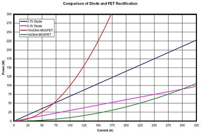
The rectification stage could be a simple diode bridge, which is cheap and good at very high currents, or a more advanced MOSFET bridge with a controller. The latter has the advantages of handling very inductive sources such as alternators in windmills, and could possibly also be used for solar MPP tracking. Also MOSFETs are less impedant at lower and medium currents.
