Torch Table Build: Difference between revisions
| Line 396: | Line 396: | ||
[[File:Work In Progress Joint.JPG| 400px|sub]] | [[File:Work In Progress Joint.JPG| 400px|sub]] | ||
<nowiki> | <nowiki> | ||
< | <eeeeeeehtml> | ||
<object width="400" height="300"><param name="allowfullscreen" value="true" /><param name="allowscriptaccess" value="always" /><param name="movie" value="http://vimeo.com/moogaloop.swf?clip_id=6967679&server=vimeo.com&show_title=1&show_byline=1&show_portrait=0&color=&fullscreen=1" /><embed src="http://vimeo.com/moogaloop.swf?clip_id=6967679&server=vimeo.com&show_title=1&show_byline=1&show_portrait=0&color=&fullscreen=1" type="application/x-shockwave-flash" allowfullscreen="true" allowscriptaccess="always" width="400" height="300"></embed></object><p><a href="http://vimeo.com/6967679">Wiggly table</a> from <a href="http://vimeo.com/user2426029">Lawrence Kincheloe</a> on <a href="http://vimeo.com">Vimeo</a>.</p> | <object width="400" height="300"><param name="allowfullscreen" value="true" /><param name="allowscriptaccess" value="always" /><param name="movie" value="http://vimeo.com/moogaloop.swf?clip_id=6967679&server=vimeo.com&show_title=1&show_byline=1&show_portrait=0&color=&fullscreen=1" /><embed src="http://vimeo.com/moogaloop.swf?clip_id=6967679&server=vimeo.com&show_title=1&show_byline=1&show_portrait=0&color=&fullscreen=1" type="application/x-shockwave-flash" allowfullscreen="true" allowscriptaccess="always" width="400" height="300"></embed></object><p><a href="http://vimeo.com/6967679">Wiggly table</a> from <a href="http://vimeo.com/user2426029">Lawrence Kincheloe</a> on <a href="http://vimeo.com">Vimeo</a>.</p> | ||
</ | </eeeeeeehtml> | ||
</nowiki> | </nowiki> | ||
| Line 449: | Line 449: | ||
So our input scale was, 8 steps/ 1.8 degrees * 360 degrees/ 1 revolution * 1 revolution / 3.14 inch = 509.29581789. The 8 steps is set via the Xylotex jumper configuration on the motor controller(default is 8 steps), the 1.8 degrees comes from the stepper motor specifications, the 1 inch comes from the outside radius of the gear attached to the stepper motor, and the rest comes from unit conversions. | So our input scale was, 8 steps/ 1.8 degrees * 360 degrees/ 1 revolution * 1 revolution / 3.14 inch = 509.29581789. The 8 steps is set via the Xylotex jumper configuration on the motor controller(default is 8 steps), the 1.8 degrees comes from the stepper motor specifications, the 1 inch comes from the outside radius of the gear attached to the stepper motor, and the rest comes from unit conversions. | ||
[http://wiki.linuxcnc.org/cgi-bin/emcinfo.pl?TweakingSoftwareStepGeneration Software step generation info] | |||
===tightening bolt pattern=== | ===tightening bolt pattern=== | ||
Because we are tensioning bolts, bearings and rail all at the same time; it is a good idea to tighten the nuts in a particular order. | Because we are tensioning bolts, bearings and rail all at the same time; it is a good idea to tighten the nuts in a particular order. | ||
| Line 458: | Line 461: | ||
< | <eeeeeeeeeeeeeehtml> | ||
<object width="400" height="300"><param name="allowfullscreen" value="true" /><param name="allowscriptaccess" value="always" /><param name="movie" value="http://vimeo.com/moogaloop.swf?clip_id=6967410&server=vimeo.com&show_title=1&show_byline=1&show_portrait=0&color=&fullscreen=1" /><embed src="http://vimeo.com/moogaloop.swf?clip_id=6967410&server=vimeo.com&show_title=1&show_byline=1&show_portrait=0&color=&fullscreen=1" type="application/x-shockwave-flash" allowfullscreen="true" allowscriptaccess="always" width="400" height="300"></embed></object><p><a href="http://vimeo.com/6967410">Calibrating using a laser</a> from <a href="http://vimeo.com/user2426029">Lawrence Kincheloe</a> on <a href="http://vimeo.com">Vimeo</a>.</p> | <object width="400" height="300"><param name="allowfullscreen" value="true" /><param name="allowscriptaccess" value="always" /><param name="movie" value="http://vimeo.com/moogaloop.swf?clip_id=6967410&server=vimeo.com&show_title=1&show_byline=1&show_portrait=0&color=&fullscreen=1" /><embed src="http://vimeo.com/moogaloop.swf?clip_id=6967410&server=vimeo.com&show_title=1&show_byline=1&show_portrait=0&color=&fullscreen=1" type="application/x-shockwave-flash" allowfullscreen="true" allowscriptaccess="always" width="400" height="300"></embed></object><p><a href="http://vimeo.com/6967410">Calibrating using a laser</a> from <a href="http://vimeo.com/user2426029">Lawrence Kincheloe</a> on <a href="http://vimeo.com">Vimeo</a>.</p> | ||
</ | </eeeeeeeeeeeeeehtml> | ||
===Dynamic Calibration=== | ===Dynamic Calibration=== | ||
Revision as of 18:33, 16 October 2009
Hot Updates
9.28.09
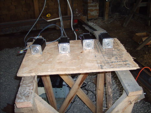
First motion of the Open Source Torch Table tested with an actuator - here a marker:
Proposal
See proposal at http://openfarmtech.org/Lawrence_Proposal.pdf .
You can also see the working agreement,Lawrence Kincheloe Contract
Working updates on the blog - [[1]]
Previous Work Torch Table
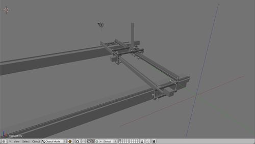
The purpose of this project is to enrich both the participant and the Factor e Farm project. The scope of this specific project is to build the seeds for a MegaRap, which is a modification of the origional Torch Table designed to expand the range of build materials and capabilities. This is in the spirit of the RepRap project, but at a larger scale and lower precision. The initial goal is to design and build a torch table that can be added on to in the future but is still functional in its own right.
Design Rationale
- High performance torch table matching and exceedings standards of commercial counterparts
- Ready adaptability to other cutting heads (router, laser, knife, etc.)
- Rack for x, y, and z motion - cheapest, most robust solution for precise motion
- Similar design in x, y, z directions
- Minimal fabrication requriments, bolt-together design
- Spring-loaded x and y motors to maintain traction
- Support under top rail with flat ball bearings to prevent the carrage from jumping the track
- Thin gauge (16 gauge) 1 inch square tubing for light weight strength
- Simple, adjustable carriage design that clamps around the 3 inch cold-rolled rail
- Ways - simplest way according to this source is bearings on cold-rolled steel.
Bill of Materials
| align="center" style="background:#f0f0f0;"|Item | align="center" style="background:#f0f0f0;"|Discription | align="center" style="background:#f0f0f0;"|Amount | align="center" style="background:#f0f0f0;"|Cost per item | align="center" style="background:#f0f0f0;"|Total per Machine | align="center" style="background:#f0f0f0;"|Total Cost | align="center" style="background:#f0f0f0;"|Further Info | align="center" style="background:#f0f0f0;"|Purpose | align="center" style="background:#f0f0f0;"|Aquired? |- | Computer with parallel port||Total computer system||1||$300 ||$300.00||$300.00 ||http://www.linuxcnc.org/%7C%7CTo run Linux cnc||yes, IBM Laptop |- | Xylotex 4 Axis Drive Box || with 4 stepper 425 oz.in. Motors and Cables||1||$460.00 ||$460.00||$460.00 ||Xylotex Stepper and controller||To provide motion control and movement precision||Yes |- | PowerPlasma 50 Plasma Torch||Pilot Arc 50 Amps||1||$699.99 ||$699.99||$699.99 ||Everlast||To provide the cutting torch for the cnc torch table||no |- | Bearing R6-2RS 3/8"x7/8"x9/3\" Sealed||10 pack||8||$14.95 ||$11.96||$14.95 ||VXB Part Number: Kit711||For preventing the carrage from jumping the track||no |- | V-Groove Bearings 3/8 inch||single pack||12||$9.95 ||$119.40||$119.40 ||VXB V-Groove bearings Part number: Kit8407||To provide low friction linear motion||no |- | 3/8 inch Hard Fiber Washers||Pack of 100||40||$2.50 ||$1.00||$2.50 ||McMaster Part Number: 95601A330||Holding bearings||no |- | Hot rolled steel 3"x1/8" plate||10.0 Ft.||5.32 ft||$12.70 ||$6.76||$12.70 ||Metalsdepot||To provide material for motor mounts||no |- | Hot rolled steel 1"x1" square tubes 16 gauge||24ft for $23.28||41.83 ft||$23.28 ||$40.58||$46.56 ||Metalsdepot||To provide structural support||no |- | Gear Rack (1/2” sq. x 72” 20 DP 20 Deg)||6 feet per rack||26.83 ft||$24.80 ||$110.91||$124.00 ||Standard Steel Specialty Part Number: 200011||rack for gear to ride on||no |- | 3 x 1/8 inch cold rolled Plate||6.0 Ft.||32.33 ft||$17.28 ||$93.12||$103.68 ||Metalsdepot||To provide material to make rails||no |- | 3/8 inch threaded rod, Overall Length 36"|| Each||11.43 ft||$1.94 ||$7.39||$7.76 ||McMaster Part Number: 98837A031||for connecting the top and bottom carage||no |- | 3/8 inch nuts||Pack of 100||112||$4.20 ||$4.70||$8.40 ||Part Number: 90473A031||For locking threaded rod in place||no |- | 3/8 inch washers||Pack of 140||112||$3.23 ||$2.58||$6.46 ||Part Number: 90126A031||For locking nuts and for spacers||no |- | Steel 20 Deg Pressure Angle Spur Gear 20 Pitch, 20 Teeth, 1" Pitch Dia, 1/2" Bore||Each||4||$15.37 ||$61.48||$61.48 ||McMaster Part Number: 5172T12||Attaches to stepper motors and interfaces with gear rack||no |- | sleeve bearing||Each||4||$1.34 ||$5.36||$5.36 ||McMaster Part Number: 6391K143||to connect between the stepper motor and the gear, will also add a bit of adjustable length||no |- | 10-32 set screw 7/16"||per Pack of 100||4||$5.44 ||$0.22||$5.44 ||Part Number: 92311A428||Set screw for attaching spur gear, sleeve bearing to stepper shaft||no |- | Zinc-Pltd Stl Pan Head Phillips Machine Screw 10-32 Thread, 1-3/4" Length|| Pack of 100||8||$8.45 ||$0.68||$8.45 ||McMaster Part Number: 90272A837||Connects the mount plate arms to the carrage||no |- | Zinc-Pltd Stl Pan Head Phillips Machine Screw 10-32 Thread, 2-1/2" Length||Pack of 100||48||$6.58 ||$3.16||$6.58 ||McMaster Part Number: 90272A840||For connecting the rail, rack, spacer and c channel||no |- | Zinc-Pltd Stl Pan Head Phillips Machine Screw 10-32 Thread, 3/4" Length||Pack of 100||24||$5.11 ||$1.23||$5.11 ||McMaster Part Number: 90272A831||For mounting the stepper motor to the mount plate||no |- | Zinc-Plated Steel Machine Screw Hex Nut 10-32 Thread Size, 3/8" Width, 1/8" Height||Packs of 100||80||$1.55 ||$1.24||$1.55 ||McMaster Part Number: 90480A195||For locking the mount plate swing tightness, tightening the rack and locking the stepper motor in place||no |- | Nylon 6/6 General Purpose Flat Washer Off-White, No. 10 Screw Sz, .44" OD,.02"-.04" Thk||per Pack of 100||32||$3.83 ||$1.23||$3.83 ||Part Number: 90295A120||allows the motor to swing freely||no |- | stepper spring||pack of 6||4||$10.00 ||$6.67||$10.00 ||McMaster Part Number: 3114T79||Prevents stepper motor shaft from crunching ||no |- | Multipurpose White Lithium Grease 10.25-Ounce Net Weight Aerosol||single pack||1||$5.62 ||$5.62||$5.62 ||McMaster Part Number: 1380K29||For greasing rails, bearings, gears, rack, etc…||no |- | Bright Finish High-Speed Stl Spiral Point Tap 10-32, H2 Pitch Diameter, 2 Flute||single pack||1||$5.26 ||$5.26||$5.26 ||Part Number: 2523A469||For tapping the 10 gauge threaded hole in the brass bushing and the steel bearing||no |- | 10 gauge drill bit||single pack||1||$1.74 ||$1.74||$1.74 ||McMaster Part Number: 2930A21||For drilling holes in rail, stepper plate, stepper plate swing||no |- | Gen Purp Black Oxide HSS Jobbers' Drill Bit 3/8", 5" L Overall, 3.1" Drill Depth, 118 Deg Point||single pack||1||$4.46 ||$4.46||$4.46 ||Part Number: 2931A34||For drilling holes in rail for threaded rod||no |- | Gen Purpose Uncoated HSS Jobbers' Drill Bit Wire GA 18, 3-1/4" Oal, 1.9" Drill Depth, 118Deg Point||single pack ||1||$1.52 ||$1.52||$1.52 ||Part Number: 30585A29||making the hole for the 10 gauge tap. It has to be slightly smaller than 10 gauge because we need to cut threading into it.||no |- | Military Spec Cadmium-Pltd Steel Flat Washer No. 10 Screw Sz, .44" OD, .03"-.07" Thk, MS27183-8||Pack of 100||1||$1.94 ||$1.94||$1.94 ||McMasters Part Number: 98032A469||Small enough to fit on the rack, big enough to do some good. General purpose metal washers for 10 gauge screws.||no |- | Total per machine||$1,960.19|||||||||||||| |- | Total Cost||$2,034.74 |||||||||||||| |}
Working Concepts
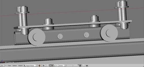
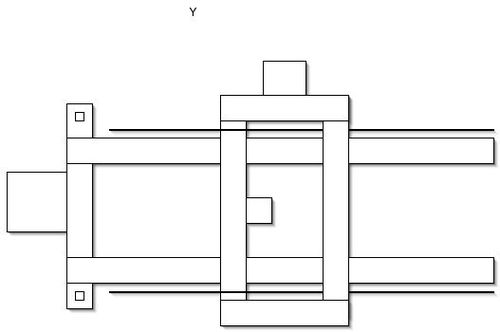
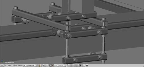
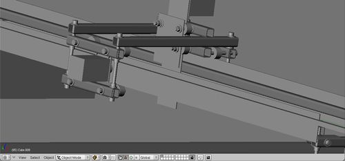
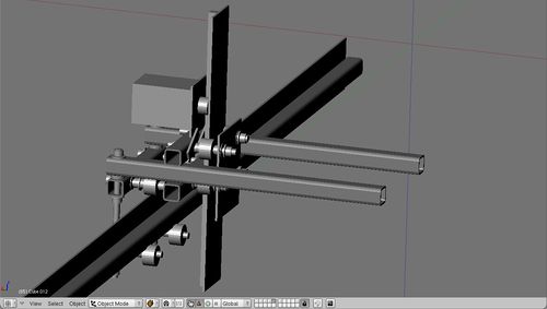
X axis
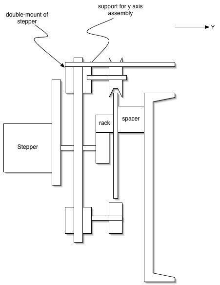
Y axis
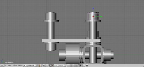
Z axis
Blender Design File Download
Blender Concept
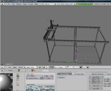 File:Factor e Torch Alpha 3.1.blend
Plasma Torch
Torch vs. Plasma Cutter
- Comes down to initial cost versus long-term cost
- Plasma cutters - consumables cost $20 for 5 new electrodes and nozzle heads
- Electrodes are rated for 45 minutes to 60 minutes for 1/2" steel
- More expensive versions state they last 4 times longer - are heavier and have better temperature control
- For anything above 1 inch, torch is better
- Can be interfaced with a computer cheaper than Torch
Desired Characteristics
We are looking for a machine rated for 1" milled steel that will cost roughly between $700-$1100. We are limited on budget because we are funded primarily through donations at the moment.
Since we want to use the machine for cnc work, we are interested in the pilot arc starting, or touch off starting. We could also use high frequency starting, but we would have to shield our motor controller and any other equipment in the area. Would it be possible to shield the plasma cutter? We want to be able to cut thin material with the torch so it is likely we will want the pilot arc starting feature.
Do you have any suggestions on a best practice method of attaching a plasma torch head on a cnc machine?
We would also be interested in a plasma cutting head that would be easier to mount. Currently in your accessories page you only list a model that is appropriate for plasma cutting by hand. Also, since this machine needs to be flexible we would also like the option of using the plasma cutting head by hand. Through looking at competitors websites, its clear that its easy to offer one or the other and switch them at the DC power inverter, but how easy would it be to add a 45 degree flexible head that can be fixed for either cnc overhang cutting or hand cutting? This seems like an easy adaption, but I might be missing something.
Also, we are interested in the engraving feature. Especially the controlled plasma pulse feature. The reason is that we are interested in precision surface removal, and gouging because we have an idea to use this machine as a plasma lathe, combined with a cnc controlled head. This isn't a requirement, but we are very interested in getting the maximum amount of utility from this tool.
Plasma Cutters Considered
- cheap ($800)
- 5 year warranty
- made in china
- cheap
- 1 year warranty
- made in america
- Out of stock/high frequency start only
- Appears to have equivalent performance to Esab Powercut 1250
- Expensive ($2700)
- Brand name
Plasma Cutter PC Interface
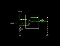
(ciruit drawn with [open source circuit simulator])
A simple relay circuit, the components depend on the plasma cutter interface. Since the Xylotex stepper controller pipes out unused pins to a second parallel port, we'll isolate the parallel port using an optoislolater and switch on a relay switch which replaces the manual torch ignition switch. If the torch allows for proportional current control, usually done with a voltage divider circuit built with a potentiometer, then we might use a pwm modulated rheostat control with the computer providing the pwm signal. If all that fails, there is alway hacking into the plasma cutter circuit board and taking over control using a microprocessor... maybe version 2.
build steps
So it turns out that because the plasma cutter comes with a pilot arc, there isn't an easy way to adjust current anyways. The reason is because the pilot arc circuit measures the current coming off the pilot arc and the work piece clamp comparing the two at low current values. Once it detects that current is flowing through the work piece clamp, it shuts off the pilot arc current pathway and ups the current for the plasma cutter. This means that there are several ways to interface with the plasma cutter circuit, but nothing out of the box. To turn on the torch head, you splice in an external switch that is controllable from the pc. To detect when the plasma cutter is good to go, you can watch for the signal pin that switches from pilot arc current to full cutting current. To adjust the cutting current, you could hijack the potentiometer from the front of the panel, which goes to the pilot arc circuit anyways. Ideally you could also tie into the voltage sensing element feedback loop of the constant current dc power supply to figure out how far away the torch head is from the surface of the work piece. This would allow for dynamic repositioning of the head.
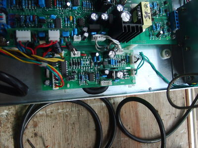
The above is the pilot arc board. We won't be touching it but for future reference, the chip File:Mc14066bcp datasheet.pdf MC14066B is a Quad Analog Switch/Quad Multiplexer which means that it is a likely candidate for investigating when it switches the reference voltage from the pilot arc to the dial setting, it probably means that the plasma cutter is ready to cut. This would make a handy "ready to cut" signal for the pc once the signal is piped out and isolated from noise.
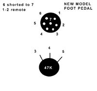
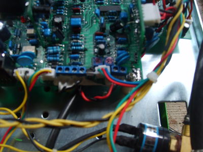
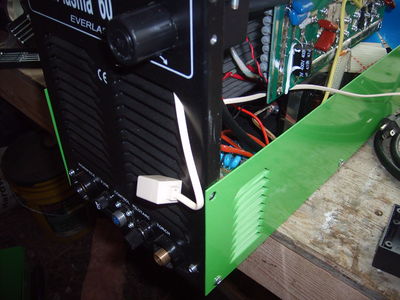
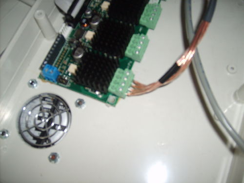
The below picture is the signal filter for the plasma cutter. Its the green circuit board in the picture. It has two extra holes where we can slip in our switch and even use the filter circuit to boot. This just means we need to add an external connector. The reason we chose not to go for a connector that fits the front plug is that the cost of that plug is prohibitive for what we want. Instead we are going to use a phone jack and wire together two pins for our interface.
The main board is where all the magic happens. We won't touch this board, but it is interesting to note that most of this plasma cutter could be replaced with a handful of microprocessors.
The data sheet for the solid state relay used File:AQV252G.pdf
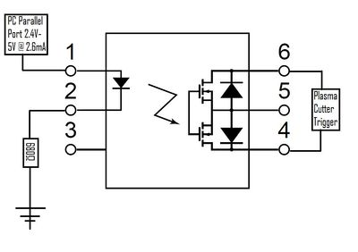
An quick overview of how this is going to work. The PC uses a parallel port that uses 0-5 volt off/on to communicate to the outside world. This has a guaranteed minimum of 2.6mA at 2.4V. Or so says the internet. The AQV252G is a solid state relay, which means it is optically isolated mosfet relay switch. This is nice because it takes care of most of the heavy lifting design wise, so all we have to do is interface with it. To do so, we essentially turn on and off a built in LED which is coupled to the mosfet. Because every parallel port is different, it would of been a smarter move to put in a variable potentiometer instead of a single resister. Unfortunately, I just thought of this, so we are going to use a 680 ohm resistor instead and hope that the voltage level for the parallel port is on the high side.
Design rational is basically, I'm treating the torch trigger like a ac/dc signal so I don't have to worry about polarity, and I can adjust the resistance until I can guarantee the parallel port can trigger on the mosfets. Detailed construction notes when all the parts arrive...
Information about PC parallel ports. [2]
Ok, parts arrived. Here is how to put it together.
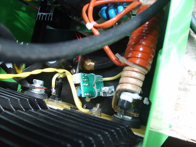
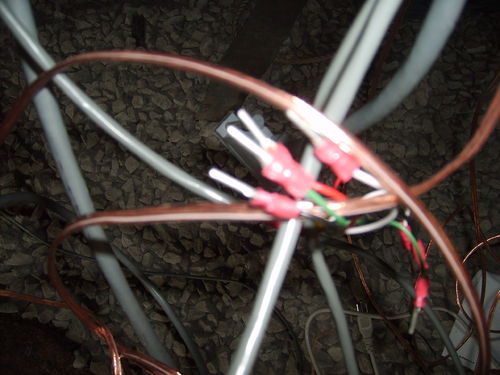
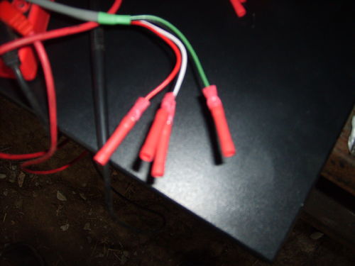
We are tyeing together two wires of the four wires in a phone wire to make a thicker wire. We only need two wires anyways. So, twist the adjoining pairs of wires so your four wires become two, tin them with solder, remove the filter board from the plasma cutter, find the input pins coming in from the torch trigger,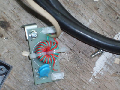
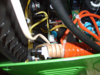
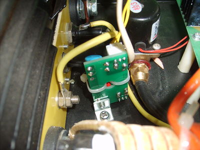
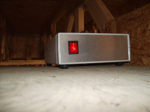
Whew, ok now on to the opto-isolated control box and pc interface.
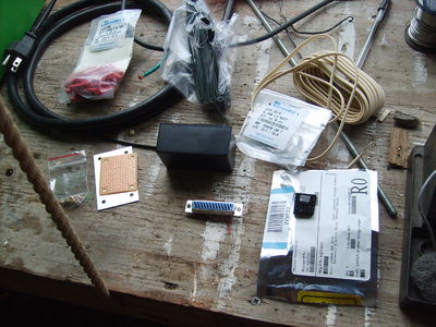
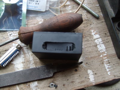
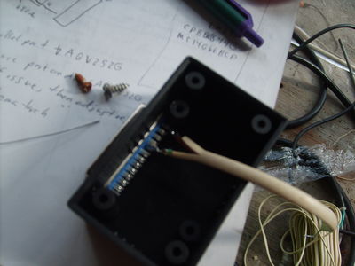
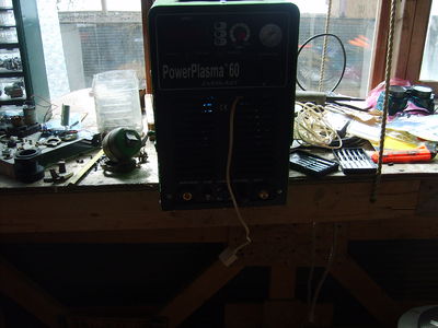
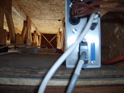 it plugs into the back of the motor controller using the same sort of cable that plugs into the pc
Motor Control
G Code
Or how I actually tell the Torch Table to move.
G Code is a loose standard. That means if you take some other G Code that you did not write, there is a good chance it will not work. The reason is that each G Code interpreter, be it EMC2, RepRap motherboard, or fancy six axis robotic arm controller were all produced for a specific job which require a specific tool path, on a specific machine. Now if your a computer scientest or programmer, your going "wait a minute, why don't they just make the language more intelligent, add in a required machine descriptor and abstract the tool path away from the user which forces users to hand craft each part they want to make!" Which is a valid point, and I would encourage someone to come up with a better language, because G Code sucks.
G Code, ala EMC2
Or how prototype 1 is put together.
link to EMC2 gcode quick lookup guide
invaluable emc2 user generated documentation wiki
Link to EMC2 gcode guide with regards to using a plasma cutter
Because we don't have an "arc stable, good to cut" we will use a delay instead which means that we'll have to find someplace on the material we can "burn into" while the arc stabilizes. This will have to be hand coded to some extent I am afraid.
There is a lot of good information in the manual which will be nessisary to hand craft g code
The other option is to use a program to generate g code from a drawing or cad software. The problem with this is that it usually does a point by point move, where a human operator could use a loop and arc move instead to achieve the same results. Furthermore, because there is no guarantee that they conform to the same g code standards as your controller, it is likely that any g code that is automatically generated will need to be tweaked first. If it isn't apparent yet, g code is time intensive to produce. Its saving grace is that once you have it, you can run the same program over and over again.
Lets take a look at the below file that was generated using Inkscape and this plugin
(Found 1 paths for AllObjects:)
G20 (All units in inches)
#1=0.5000 (Height to traverse when not cutting)
#2=0.0000 (Height to cut at)
#3=10.0000 (Tool feed rate)
#4=1.0000 (X axis scale factor)
#5=1.0000 (Y axis scale factor)
(Path has size 36.000 x 54.000)
(Path has bounding box 4.500-40.500 wide by 4.000-58.000 high)
G00 Z#1
G00 X[4.5000*#4] Y[58.0000*#5]
G00 F#3 Z#2
G01 X[4.5000*#4] Y[58.0000*#5]
G01 X[36.0000*#4] Y[58.0000*#5]
G01 X[4.5000*#4] Y[35.5000*#5]
G01 X[40.5000*#4] Y[31.0000*#5]
G01 X[13.5000*#4] Y[13.0000*#5]
G00 Z#1
G00 X[0.0*#4] Y[0.0*#5]
M2
This program has options for some basic conveniences, but its true power is that is allows for a simple conversion path from a drawn path to actual g code. That being said, I wouldn't use it for anything more complex than making holes and contours. Luckily thats what most people want it for.
For example, the # with a number following allows for macro variable replacement, so minor changes, like going from millimeter to inches, isn't such a pain.
More info can be had at by looking to the emc2 manual for information on G code.
Other sources for g code generated goodness. TBC
Xylotex
RepRap
The RepRap project uses 12v stepper boards. These are roughly comparable with the Xylotex stepper control package. The difference is that Xylotex can step at 1/8th of a 1.8 degree step per pulse, and RepRap can step at 1/4th of a 1.8 degree step per pulse. Xylotex also has a total higher wattage potential at 24V 2A, but RepRap which runs at 12V 2A should be enough to hit the optimal energy density of the stepper motors. The only thing I would add would be a heat sink and a fan to the RepRap stepper driver so we can work the motor driver harder. Version 2 will most likely try to either incorporate a redesigned RepRap motor driver that can do 1/8th stepping or live with the standard 1/4th stepping. It is yet to be seen how useful 1/8th stepping is in practice. [3]
Linux CNC
[LinuxCNC]
The Setup
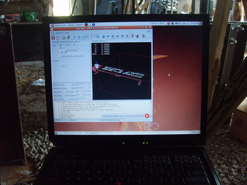
We are as of Sept. 4, 2009 using an IBM ThinkPad laptop graciously donated to the cause by Inga. It has the latest EMC2 installed from the Ubuntu 8.04&EMC2 Live CD.
If your starting from a pre-existing Linux install, like I was, then read this important user contributed wiki. I had to reinstall using the 8.4 live cd because 8.10 of Ubuntu wasn't supported.
Once you get that all installed, the best documentation available is from the user contributed wiki and the included manuals. For example, when I had trouble with getting the IBM laptop to talk to the motor controller, I used [this walk-through] to step me through a working install which lead me to the actual problem of the IBM laptop having a non-standard printer port address.
Once I got the stepper motors twitching to my every whim, I put it all down and will continue from where I left off once I get the little beasties mounted.
Torch Table Trouble Shooting
For those extra hard to reach bugs
- Check stepper motors
- They should turn when powered off, so the whole table should move freely. If it doesn't fix it.
- When the motor controller is powered on, with the PC disconnected, the stepper motors should be locked in place or provide significant resistance.
- If everything checks out, the motor driving circuitry and the stepper motors are at least working correctly.
- Check the PC parallel port.
- You can do this with a multimeter and LinuxCNC. If you test one of the pins under control and its jumping around like crazy then the computer is at the least sending something with the parallel port
- There are options to change the parallel port address from the default. In the case of the IBM laptop, the parallel port was 3BCH, which is a hex value.
- Check the pinout of the cable.
- In our case we used a shielded straight pass through cable, which means each pin on either side corresponds to its matched up pin on the male/female connector.
- If its different than what you think it should be, according to whatever motor controller your using. You can adjust the pin out in EMC2. Look up how to do this.
- Check installed version of Linux.
- In the version we used, there was an issue where the kernel drivers for 8.4 weren't compatible with 8.10 and above. This means that it installed fine but there wasn't an option for using the special real time EMC2 kernel. The fix is to reinstall using either the live CD which will leave you with a clean Ubuntu install with the software already installed (very convenient if it works), or installing from scratch Ubuntu 8.4 and installing the package seperately from [[4]]
Build Steps
This table uses standard stock steel parts with no finishing besides the finishing that is required.
If you caught that, then you have two options. Find a local machine shop to cut out all that steel you just purchased or live with some inaccuracies which should be adjustable.
Necessary Tools
- Something to cut accurate holes with
- Something to cut 3/8 inch treaded rod, 1/8 inch hot rolled steel plate, 1 inch tubing, etc...
Tools We Used
- Drill Press
- Hand Drill
- Metal File
- Phillips Screw Driver
- Flat Head Screw Driver
- Wrench able to fit up to 5/8 inch bolt heads and down to 1/8 inch nuts
- 3/8 inch drill bit
- 1/2 inch drill bit
- 10 gauge drill bit
- 10 gauge tap
- bubble level
- Builders Square
- Tape Measure
- Saw Horse
- C Clamps; two of each 3 inch, 4 inch, 6 inch
- friction jaw clamps
- wood spacers
Building a Jig
Yes its a technical term.
For our purposes we need a reliable way to drill somewhat precise holes quickly.
To do this we need to constrain the rack in the x y and z direction during drilling but allow movement along the y axis to reposition the rack for the next hole. In this example, the direction along the length will be our y axis.
There are several products out there that will do what we want, but they all need to be modified slightly for our purposes.
For drilling the holes, you'll need a guide made out of something that won't mar the metal. Wood or plastic works nicely. If you have a vice or an x/y milling vice, these will work nicely although you'll have to make some sort of insert so the gear rack can slide easily in the vice channel. Here again wood or plastic are your friends.
If you don't have a vice and you do have some wood and some nuts and bolts that fit the mounting holes in your vice, you can make a temporary jig with blocks of wood which have to be aligned such that the drill head is above the rack, doesn't crater into the mounting plate (unless your wise enough to put a spacer block under the rail) and constrains the rail in the x direction while allowing free movement in the y direction. It'll take some practice but once you get it, you can use the same setup for all the rack.
The process is fairly simple, you mark your first hole on the rack and then every succeeding hole, you measure 8 inches (what we used) from the center of that hole. This can be achieved by adding a guide which you line up the center of the hole you just drilled with the guide such that the drill bit is over the next spot and the last drill hole you made is 8 inches away.
Lastly, you clamp down the rack in the z direction such that frictional forces and the wood blocks help constrain the rack for drilling. Releasing the clamp slightly until the rack is movable along the y direction again allows you to position the rack for the next hole to be drilled.
This documentation is quite good. The procedure for joing rack pieces, and for making a rack-CR-tube assembly should also be shown. Other than that, this is pretty impressive - MJ.
The Table
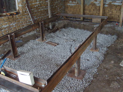
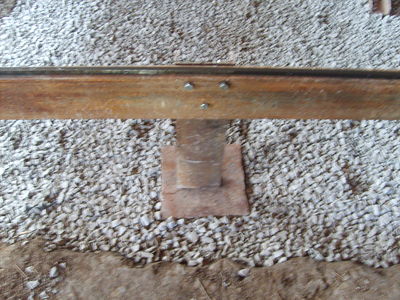
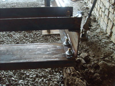
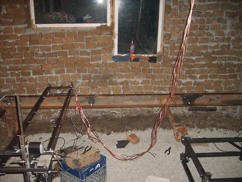
To correct the wiggle, the legs were moved to the corners of the table.
The 3/8 inch threaded rod
Get all the 3/8 nuts lined up. This allows you to cut the rod to size and use the nut to reshape the cut threads.
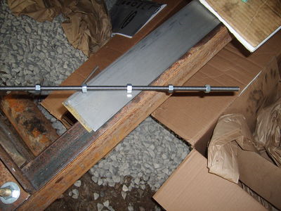
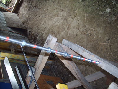
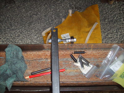
The Motors
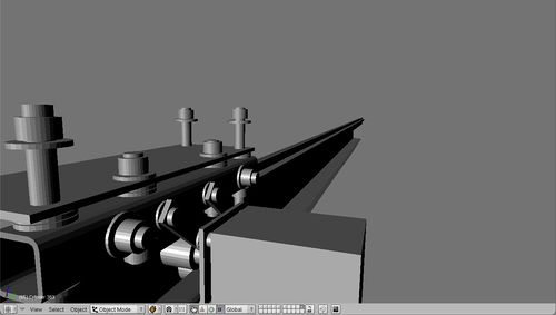
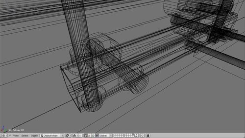
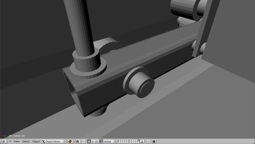
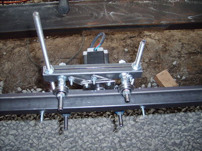
To make one of the motor carriages, we used a steel gear head with a brass insert to get the inner diameter size we needed.
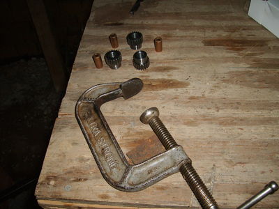
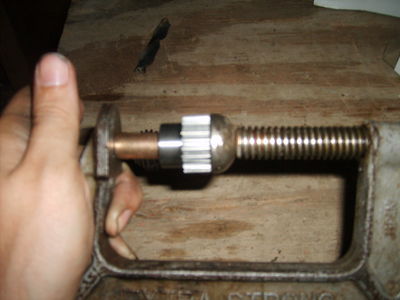
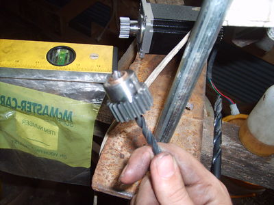
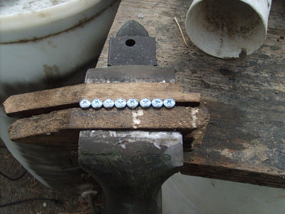
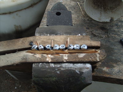
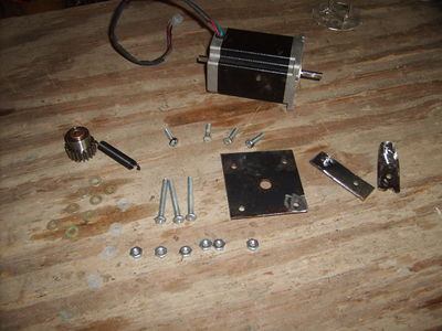
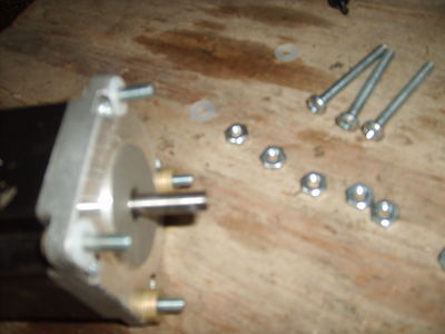
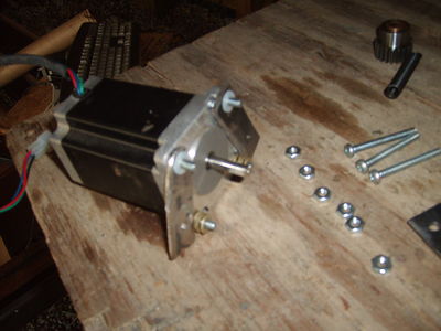
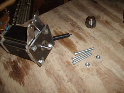
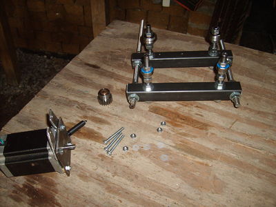
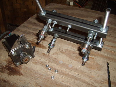
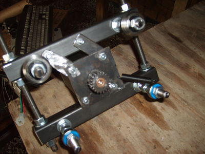
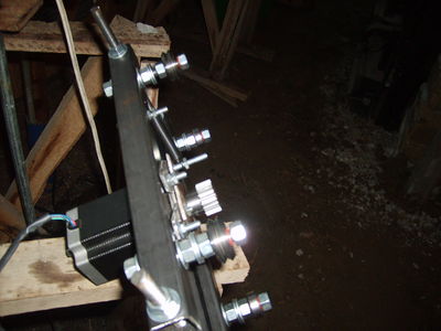
Calibration
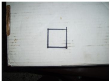
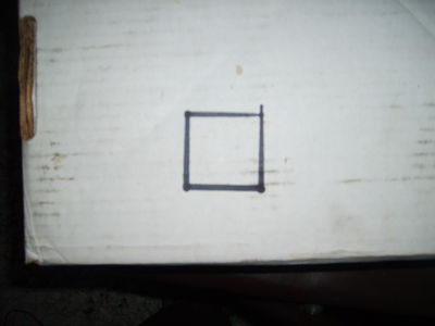
Test square looks good. Only problem was that the step size was supposed to be 1/4 of that.
EMC2 motor scale
One problem turned out to be that the software was expecting half stepping and the stepper board was expecting eighths stepping.
According to the EMC2 Scale documentation, input scale = (# steps / degree precision of stepper motors) * (360 degrees/revolution * # revolutions / inch)
So our input scale was, 8 steps/ 1.8 degrees * 360 degrees/ 1 revolution * 1 revolution / 3.14 inch = 509.29581789. The 8 steps is set via the Xylotex jumper configuration on the motor controller(default is 8 steps), the 1.8 degrees comes from the stepper motor specifications, the 1 inch comes from the outside radius of the gear attached to the stepper motor, and the rest comes from unit conversions.
tightening bolt pattern
Because we are tensioning bolts, bearings and rail all at the same time; it is a good idea to tighten the nuts in a particular order. The reason is to give better distribution of force over the entire member. In general, pick a point that is affected by gravity near the top and tighten it such that it is finger loose. Then pick its farthest companion bolt, (usually diagonally from origional bolt) and tighten it finger tight as well. Continue tightening bolts that are holding weight due to gravity and continue to select the bolt that will most greatly effect its adherence to the surface. Usually this ends up with a top left, bottom right, top right bottom left pattern. Continue tightening in 1/3 turn increments until the proper tensioning has been achieved.
Shooting lasers for fun and calibration
Using a laser to help characterize motion is a fast and easy way to figure out how level something is. It can be used to determine how flat a surface is by sprinkling salt on a table and using a refracting lens that produces a laser line to shine on the sheet sideways. The desired effect is to light up every grain of salt. Dips and bumps will show up as places where the salt crystals don't glow red.
It can also be used in a similar manner to characterize how smooth the motion of travel over the length of the table by using a similar method. Using a straight beam of laser light, shine it along the axis of motion, such that the beam hits a scattered field of salt. For ease of reading, you can brush away unlit salt. Ideally there should be several places along the beam that you can use to help increase accuracy. Now move the table slowly so as not to disrupt the salt crystals and watch for crystals blinking out. If you find them blinking out, move the gantry back and record the point on the table the curve is happening. This indicates a place where some sort of bend is. Continue measuring and detect if the salt crystals ever become lit again. If they do, then its a bowing distortion which needs to be flattened by pulling it tight. If ti doesn't come back, then its a curve and something is causing the path to diverge. It could be dirt between the rail and the table, or it could be something major like a misaligned screw hole.
<eeeeeeeeeeeeeehtml>
<object width="400" height="300"><param name="allowfullscreen" value="true" /><param name="allowscriptaccess" value="always" /><param name="movie" value="http://vimeo.com/moogaloop.swf?clip_id=6967410&server=vimeo.com&show_title=1&show_byline=1&show_portrait=0&color=&fullscreen=1" /><embed src="http://vimeo.com/moogaloop.swf?clip_id=6967410&server=vimeo.com&show_title=1&show_byline=1&show_portrait=0&color=&fullscreen=1" type="application/x-shockwave-flash" allowfullscreen="true" allowscriptaccess="always" width="400" height="300"></embed></object>
<a href="http://vimeo.com/6967410">Calibrating using a laser</a> from <a href="http://vimeo.com/user2426029">Lawrence Kincheloe</a> on <a href="http://vimeo.com">Vimeo</a>.
</eeeeeeeeeeeeeehtml>
Dynamic Calibration
There is also the option of using a touch off pad that has a conductive probe or a switch that allows for the tool head to come down. Here is a link to an example. Another idea is to get a dual position momentary contact switch that is calibrated to be in the range of the optimal torch head distance. That way the calibration stick is depressed into the material and follows the contour of the material. the torch head stays between the two contact zones so it can back off if it begins to get out of bounds. The tolerance isn't great but would make an easy addition.
Review
Please submit comments here. Please review our design rationale first.
Particular points:
- Suitability of 3x1/8" cold rolled rail as a guide
- Suitability of thin gauge 1" square tubing for most of the gantry
- Structural or stability issues?
- Acceleration issues?
- Feasibility of using a laptop and compromises therefrom?
- run [realtime latency test] before getting too attached - laptops are notorious for hardware timing glitches.
- Lawrence: Performed, just not documented. We were getting in the 30-50 micro seconds range which is acceptable for right now. We have several other computers but the laptop was the only one that didn't have an immediate hardware issue.
- dust generated by plasma will get in keyboard and fan, wear out quickly. hard to replace laptop parts.
- Lawrence: Good catch. this is especially relevant since the recommended parallel cable length is 3 feet to 6 feet and the motor controller box itself has rather shortish cables. The ideal solution is to use something that is more robust and able to be isolated like an embedded processor in an enclosure. Best for version two. for now however,the best option will probably be a dust cover for an external keyboard and a foam fan filter for the motor controller and final pc configuration.
- run [realtime latency test] before getting too attached - laptops are notorious for hardware timing glitches.
- Suitability of plasma cutter?
- Potential improvements?
Team
- Deep in the continental US underground...
