CNC Torch Table/Manufacturing Instructions
| CNC Torch Table | ||
|---|---|---|
| Home | Research & Development | Bill of Materials | Manufacturing Instructions | User's Manual | User Reviews | 
| |
Prototype 2
Fabrication of Prototype 2 was started in the summer of 2012. It is a great improvement from the first prototype. The following team is highly reccomended for replication:
- 1 to 3 people dedicated to fabrication and machining
- 1 person dedicated to electronics
- 1 person dedicated to software
- 1 person to understand how everything fits together, and to work with the other three members to quickly solve any dilemas or problems that arise.
Summary of Steps
The following fabrication steps can be done in parrallel to expedite replication.
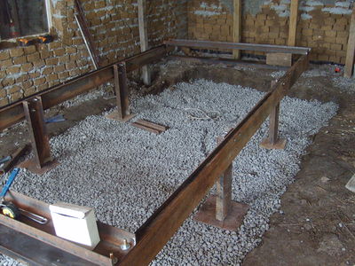
- Structural Components
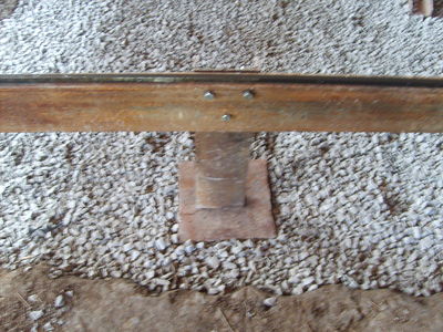
- Table Legs
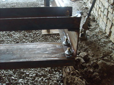
- Table Frame
- Sacraficial Slats
- X-Tracks and Spacers
- Y-Axis (gantry)
- Mechanical Components
- Z-Axis
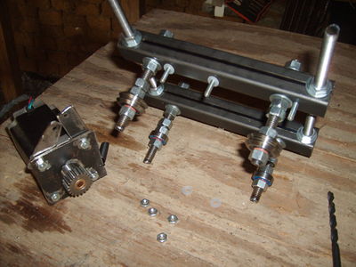
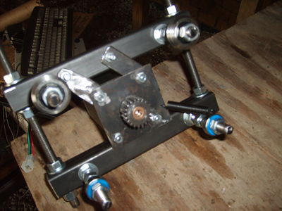
- Stepper Motor Mounts
- Electrical Components
- Stepper Motors
- Arduino Wiring
- StepperNug
- Software Components
- Operating System
- DXF-to-GCode Conversion software
- Arduino Input Software (promts user for Gcode and sends instructions to stepper motors)
Necessary Tools
(todo) (divide by electronics and machining)
Detailed Instructions (videos)
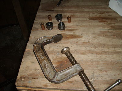
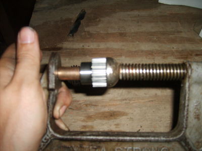
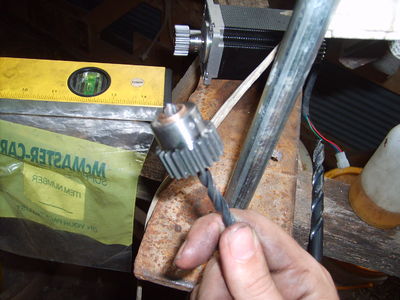
Stepper Motor Gear Reduction and Pinion
Pinion Video
Height Adjustment Legs Video
Leg Video
Prototype 1
Necessary Tools
- Something to cut accurate holes with
- Something to cut 3/8 inch treaded rod, 1/8 inch hot rolled steel plate, 1 inch tubing, etc...
Tools We Used
- Drill Press
- Hand Drill
- Metal File
- Phillips Screw Driver
- Flat Head Screw Driver
- Wrench able to fit up to 5/8 inch bolt heads and down to 1/8 inch nuts
- 3/8 inch drill bit
- 1/2 inch drill bit
- 10 gauge drill bit
- 10 gauge tap
- bubble level
- Builders Square
- Tape Measure
- Saw Horse
- C Clamps; two of each 3 inch, 4 inch, 6 inch
- friction jaw clamps
- wood spacers
Building a Jig
Yes its a technical term.
For our purposes we need a reliable way to drill somewhat precise holes quickly.
To do this we need to constrain the rack in the x y and z direction during drilling but allow movement along the y axis to reposition the rack for the next hole. In this example, the direction along the length will be our y axis.
There are several products out there that will do what we want, but they all need to be modified slightly for our purposes.
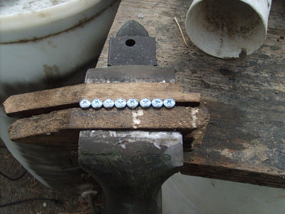
For drilling the holes, you'll need a guide made out of something that won't mar the metal. Wood or plastic works nicely. If you have a vice or an x/y milling vice, these will work nicely although you'll have to make some sort of insert so the gear rack can slide easily in the vice channel. Here again wood or plastic are your friends.
If you don't have a vice and you do have some wood and some nuts and bolts that fit the mounting holes in your vice, you can make a temporary jig with blocks of wood which have to be aligned such that the drill head is above the rack, doesn't crater into the mounting plate (unless your wise enough to put a spacer block under the rail) and constrains the rail in the x direction while allowing free movement in the y direction. It'll take some practice but once you get it, you can use the same setup for all the rack.
The process is fairly simple, you mark your first hole on the rack and then every succeeding hole, you measure 8 inches (what we used) from the center of that hole. This can be achieved by adding a guide which you line up the center of the hole you just drilled with the guide such that the drill bit is over the next spot and the last drill hole you made is 8 inches away.
Lastly, you clamp down the rack in the z direction such that frictional forces and the wood blocks help constrain the rack for drilling. Releasing the clamp slightly until the rack is movable along the y direction again allows you to position the rack for the next hole to be drilled.
This documentation is quite good. The procedure for joing rack pieces, and for making a rack-CR-tube assembly should also be shown. Other than that, this is pretty impressive - MJ.
Drill Prep
- Oil rails to allow smooth motion in the jig
- Position loose blocks of jig
- use c clamps to force the jig against table surface
- make sure the 6 foot rack is well supported and is level with the drill table
- use c clamps and a spacer if nessisary to keep the rail clamped in between the jig and the drill table. (otherwise the rail can lift up off the table and the holes drilled won't be straight)
- slightly loosen all the c clamps such that an oiled rail can move freely in the jig.
- Now tighten up the jig, while leaving the c clamp that prevents the rail from wandering up such that the rail can still move back and forth.
- Make a shallow test indention and make sure that the drill bit isn't wandering and the hole lays between the bottom of the teeth and the edge of the rail. If you make a mistake, favor the edge of th rail.
- lock the drill press, rail, etc in place and begin drilling slowly.
The Table
The table uses half inch bolts. In the future, use four bolts instead of three, put the legs at the end of the table, add legs that have feet that are wide on all sides on the bottom, and frankly, never use this table design. Its too heavy to manufacture by one person and doesn't have any outstanding benefits besides "life time design" which is a fancy way of saying the damn thing will never be moved.
Wiggly table from Lawrence Kincheloe on Vimeo.
To correct the wiggle, the legs were moved to the corners of the table.
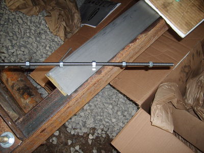
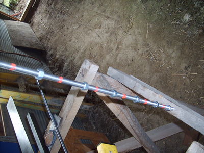
The 3/8 inch threaded rod
The Motors
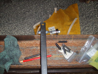
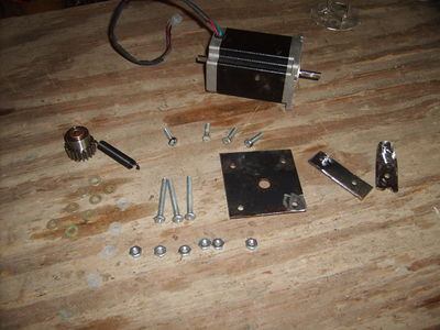
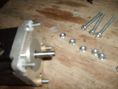
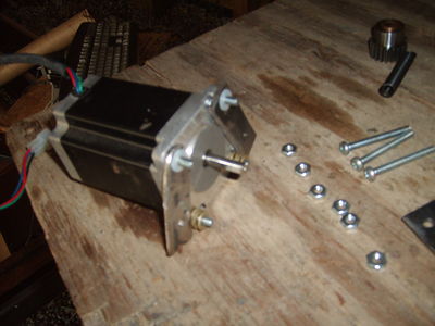
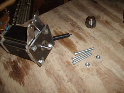
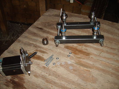
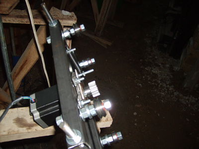
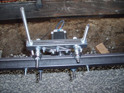
Quick note on corrections and motor info. In the final design we switched from using nylon thrust bearings to ball bearing thrust bearings. This greatly decreased fristion under load and allowed the arms to work properly. The purpose of the arms is to allow the motors to slip before becoming damaged. Because of this modification, we redesigned the motor mount arrangement such that the motor mount had one metal washer and one nylon washer. This allowed for very good spacing between motor and mount plate. Another note, get screw heads that fit with the motor mount holes. While we are on the topic, also instead of using the arms which are nifty and cool, use one long moment arm instead. It will drop the number of thrust bearings required from 8 to 2. Those thrust bearings aren't cheap so be warned.
Motor specs
Axil 1/4 inch diameter, 7/8 inch in length
Holes are a size 10
Photos of table, including measurements
Calibration
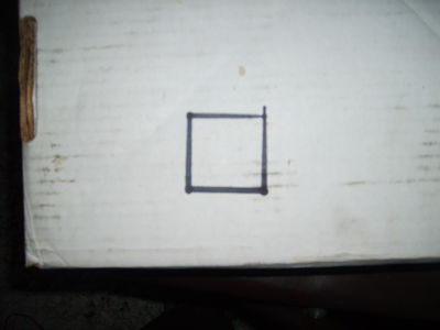
Test square looks good. Only problem was that the step size was supposed to be 1/4 of that.
EMC2 motor scale
One problem turned out to be that the software was expecting half stepping and the stepper board was expecting eighths stepping.
According to the EMC2 Scale documentation, input scale = (# steps / degree precision of stepper motors) * (360 degrees/revolution * # revolutions / inch)
So our input scale was, 8 steps/ 1.8 degrees * 360 degrees/ 1 revolution * 1 revolution / 3.14 inch = 509.29581789. The 8 steps is set via the Xylotex jumper configuration on the motor controller(default is 8 steps), the 1.8 degrees comes from the stepper motor specifications, the 1 inch comes from the outside radius of the gear attached to the stepper motor, and the rest comes from unit conversions.
tightening bolt pattern
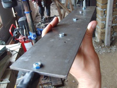
Because we are tensioning bolts, bearings and rail all at the same time; it is a good idea to tighten the nuts in a particular order. The reason is to give better distribution of force over the entire member. In general, pick a point that is affected by gravity near the top and tighten it such that it is finger loose. Then pick its farthest companion bolt, (usually diagonally from origional bolt) and tighten it finger tight as well. Continue tightening bolts that are holding weight due to gravity and continue to select the bolt that will most greatly effect its adherence to the surface. Usually this ends up with a top left, bottom right, top right bottom left pattern. Continue tightening in 1/3 turn increments until the proper tensioning has been achieved.
Dealing with loose bolts
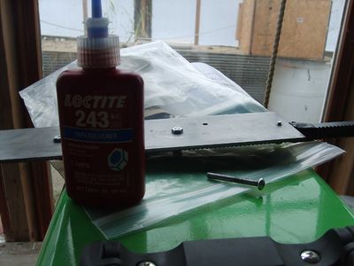
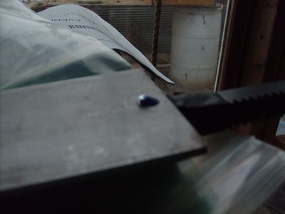
One problem that always comes up when using nuts and bolts, is that they tend to come apart. They make special screws and nuts that have built in washers and beveled grooves which dig into the metal, but we didn't use any of these. Instead we used thread lock which can be used in conjunction with the above special parts for extra grip. We purchased Loctite® Threadlocker & Retaining Compound Loctite® 243 Threadlocker Adhesive, .34 oz, Blue, which is formulated to be removable with hand tools and can be applied to parts that have some oil on them. I didn't want to degrease every nut and bolt, and using a thread locker, means I just have to loosen the nut enough to apply the blue goop.
Shooting lasers for fun and calibration
Using a laser to help characterize motion is a fast and easy way to figure out how level something is. It can be used to determine how flat a surface is by sprinkling salt on a table and using a refracting lens that produces a laser line to shine on the sheet sideways. The desired effect is to light up every grain of salt. Dips and bumps will show up as places where the salt crystals don't glow red.
It can also be used in a similar manner to characterize how smooth the motion of travel over the length of the table by using a similar method. Using a straight beam of laser light, shine it along the axis of motion, such that the beam hits a scattered field of salt. For ease of reading, you can brush away unlit salt. Ideally there should be several places along the beam that you can use to help increase accuracy. Now move the table slowly so as not to disrupt the salt crystals and watch for crystals blinking out. If you find them blinking out, move the gantry back and record the point on the table the curve is happening. This indicates a place where some sort of bend is. Continue measuring and detect if the salt crystals ever become lit again. If they do, then its a bowing distortion which needs to be flattened by pulling it tight. If ti doesn't come back, then its a curve and something is causing the path to diverge. It could be dirt between the rail and the table, or it could be something major like a misaligned screw hole.
Calibrating using a laser from Lawrence Kincheloe on Vimeo.
Dynamic Calibration
There is also the option of using a touch off pad that has a conductive probe or a switch that allows for the tool head to come down. Here is a link to an example. Another idea is to get a dual position momentary contact switch that is calibrated to be in the range of the optimal torch head distance. That way the calibration stick is depressed into the material and follows the contour of the material. the torch head stays between the two contact zones so it can back off if it begins to get out of bounds. The tolerance isn't great but would make an easy addition.
