Power Cube VII: Difference between revisions
Tom Griffing (talk | contribs) |
Tom Griffing (talk | contribs) |
||
| Line 181: | Line 181: | ||
* Weld two more pieces to the squares | * Weld two more pieces to the squares | ||
* Weld the two haves to form a cube | * Weld the two haves to form a cube | ||
<html><iframe width="420" height="315" src="https://www.youtube.com/watch?v=R5LeUW0WXPk" frameborder="0" allowfullscreen></iframe></html> | <html><iframe width="420" height="315" src="https://www.youtube.com/watch?v=R5LeUW0WXPk" frameborder="0" allowfullscreen></iframe></html> | ||
Revision as of 03:40, 21 December 2014
Assembly Video: Power Cube Assembly

Introduction
The purpose of Power Cube is to supply hydraulic fluid power for other machines. While the Power Cube designs are meant to be scalable, this design uses a 28 HP engine and hydraulic components that have proven to work well with OSE machines.
Power Cube VII marks the next level of modularity in the power cube with quick-connected: engine assembly, pump assembly, hydraulic tank, fuel tank, control panel. This is on top of the hydraulic quick connects that allow the power cube to function as a power module for any power equipment in the Global Village Construction Set.
Development
The Power Cube has gone through a series of updates and this page reflects the current designs of Version 7 of the Power Cube.

This design has proven to work well and has had few updates lately. Here are the latest updates:
Oct 2014: Added a pressure relief valve and associated plumbing - TLG.
Oct 2014: Changed sight gauge to shorter model and moved above the suction strainer for greater visibility - TLG.
Files for Power Cube VII
Sketchup
please upload new version by clicking on existing version - the wiki has file versioning
- Latest file (see revision history for versions) - File:Power Cube VII.skp
- July 4, 2014 - File:Power Cube VII July.skp
- June 2014: File:Power Cube VII June.skp
- May 2014: File:Power Cube VII.skp
Bill Of Materials (BOM)
- Latest BOM: File:Power Cube VII BOM.pdf
Module Drawings
- Control Panel File:Control Panel.skp
- Control Panel Assembly File:Control Panel Assy.skp
- Oil Cooler File:Oil Cooler.skp
- Frame File:Frame.skp
- Fuel Tank File:Fuel Tank Assy.skp
- Hydraulic Reservoir File:Hydraulic Reservoir.skp
- Wiring Harness File:Frame.skp
Power Cube Working Document
Document: ["https://docs.google.com/presentation/d/1oJbd8zQPIdDcFlyZn8Gj6_swQh8RWOkQLQ6hae8pHZ0/embed?start=false&loop=false&delayms=3000"]
Fabrication Steps
The Power Cube is assembled from a variety of modules and the fabrication begins with the modules, then completed by integrating the modules. The order of module fabrication is not important, as long as they are completed for the final integration.
The modules are detailed below:
Fuel Tank Module
- Drawings: media:Fuel_tank.pdf, media:Fuel_tank_assy.pdf
- Cut Steel: 6" x 12" tube and 2 each: 1/4" x 6" x 12", 1/4" x 4" x 4" and 1/4" x 1" x 4"
- Cut holes in tube per drawing (drill small hole, torch large hole)
- Test that fuel pickup fits in small hole - grind / file hole to fit
- Grind ends of tube square if cut with torch
- Weld end plate to tube end nearest fuel filler
- See note below for welding: Hydraulic_Reservoir_and_Fuel_Tank
- Weld fuel filler neck (use low setting for thin steel)
- Assemble Fuel Pickup
- Insert tube into compression fitting and tighten hand-tight, then wrench-tighten 1/2 turn. Loosen and set the tube part down. Wrap teflon tape on threads of hose barb and thread into top of compression fitting and tighten (don't overdo it: we're working with brass).

- Let tank cool, apply gasket sealant to smaller hole and install fuel pickup
- Reach inside the open end of the tank with tube, align with hole and screw top of compression fitting from above, then tighten.
- Weld remaining end plate
- Weld mounting brackets together, then to tank (do not weld inside edge of bracket)


- Weld control panel bracket to tank
- Weld bolts to tank, using upper pump plate for alignment
- Put cap on fuel filler and rubber hose on hose barb. Pressure test with compressed air and soapy water and re-weld as necessary until all leaks stopped.
- Paint entire fuel tank except for hose barb, top of fuel filler and cap.

Hydraulic Reservoir
- Drawings: media:hyd_reservoir.pdf, media:reservoir.pdf
- Drawings: media:reservoir.pdf, media:reservoir_assy.pdf
- Cut Steel: 6" x 12" tube and 2 each: 1/4" x 6" x 12", 1/4" x 4" x 4" and 1/4" x 1" x 4"
- Cut holes (drill small holes, torch large holes)
- Check that the corresponding parts fit properly in the holes (they may need to be ground / filed a bit)
- Grind tube ends square
- Clean all edges for welding
- Weld tank flanges and half coupling for suction port
- Weld end plate to tank end nearest the sight gauge holes
- See note below for welding end plates: "Hydraulic Reservoir and Fuel Tank"
- Mount sight gauge
- Weld remaining end plate (First check that sight gauge is installed!)
- Plug all flange holes, drill a hole in the 1 1/2" cap for the suction port and plug with a tire stem valve. Pressure test with compressed air and soapy water and re-weld as necessary until all leaks have stopped.
- Weld mounting brackets together (do not weld inside edge of brackets)
- Weld brackets to tank (use 1/4" x 2" x 26" steel as spacer under brackets)
- Weld bolts to tank (use top pump plate to align bolts)
- Paint entire tank except for threads and sight gauge.

Engine Module
- Drawings: media:engine.pdf
- Cut plate: 8“ x 15 1/2“, grind edges
- Torch and grind large holes
- Drill small (5/16“) holes, grind slots
- Paint plate, let dry
- Bolt plate to engine
- Bolt muffler to engine with gaskets between muffler and engine ports
- Bolt muffler extension to muffler with 1 1/2" "U" bolt

- Shaft Coupler
- Cut both shaft couplings in half, set aside one half of each coupling
- Insert alignment plug, clamp end-to-end with C-clamp and weld couplers together
- Note: Touching coupling faces should be machined faces (not cut faces)
- Remove plug (use hammer & blunt punch)
- Let cool, then insert key into engine shaft slot, then secure coupling to engine shaft with set screw
- Note that once engine is mated with pump, the shaft coupler should be checked to insure that it fully engages teeth of pump shaft. This may require loosening the set screw and sliding the coupler down - but don't let it rest against pump casing.

Pump Module
- Drawings: media:pump.pdf, media:pump_assy.pdf
- Cut plates and angle iron
- Torch large holes, drill small (5/16“) holes
- Grind edges, test fit pump & bolts
- Space angle iron evenly on 6“ plate as shown below, 1/4 from edges. Tackweld inside corner of angle iron, then outer corners
- Weld outer and inner edges

- Stack pump plates as shown in diagram below (pay attention to 3/4" holes in larger plate)
- Add 4 1/4" spacers between plates as shown
- Note: Spacers should provide 1/8" standoff from other angle iron and have VERY perpendicular and smooth edges
- Use two C-clamps to clamp plates securely to spacers - they should be directly inline with spacers
- Precision note: Plates must be parallel else shaft may bind. Before welding, check that plates are spaced evenly.
- Tackweld inside corners (do not weld spacers)
- Weld inside and out, remove clamps & spacers

- Bolt pump to plate assembly
- Install hosebarb on pump
- Install elbow on pump loosely
- Note: keep holes on pump plugged to prevent debris

Oil Cooler Module
- Drawing: media:oil_cooler.pdf
- Carefully unbox oil cooler
- Wrap NPTM elbow threads with teflon tape
- Screw NPTM ends of elbows into cooler, tighten so JIC elbow ends point as in illustration
- Secure fan to cooler

Control Panel Module
- Torch large holes, drill small holes
- File key hole to fit switch
- Grind all edges
- Weld bracket for throttle
- Install throttle and keyswitch
- Install quick connectors using teflon tape


Frame Module
- Drawing: media:PCVII_frame.pdf
- Cut angle iron, flat bar, rebar and expanded steel
- Grind ends of angle iron at 45 degrees
- Align and weld 4 “V“s from angle iron
- Align and weld “V“s to form two squares
- Weld two more pieces to the squares
- Weld the two haves to form a cube
Media:Frame_Construction.mp4
- Weld the battery box and tank supports
- Weld the expanded steel in place
- Bend the rebar segments into "U" shaped hoist hooks
- Weld the the hoist hooks and QA plates

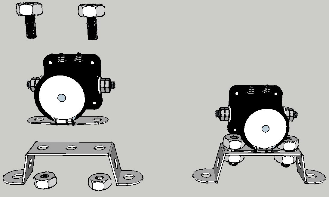
Solenoid Module
- Drawing: media:Solenoid Module.png
- Bend one cooler support to match holes on fuel tank
- Mount solenoid on support braket (made above)


Wiring Harness
- Drawing:
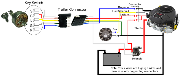

- Photo:
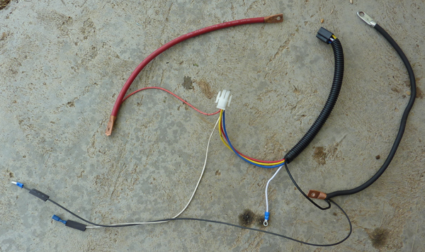

Battery Terminals
Engine Connections
Final Assembly
- Install Fuel Tank module in frame (fuel tank goes beside battery box)

- Install Hydraulic Reservoir module in frame

- Install Pump module and Solenoid module

- Install oil cooler and fan to expanded steel

- Install hoses to connect hydraulics and tighten appropriately
- Install Wiring Harness to key switch, connect to fan and solenoid (do not connect "+" battery connection yet)
- Install Engine module:
- Lower Engine Module gently until shaft coupling contacts pump shaft, rock/turn engine until shaft engages pump
- Install 3/4" bolts / washers / nuts, securing engine plate to pump plate
- Remove nut from right rear engine bolt, place black battery on bolt, replace nut and tighten
- Connect electrical connector from wiring harness to engine
- Connect fuel hose from fuel tank to engine
- Connect cable from solenoid to starter and tighten carefully
- Install battery in battery box
- Connect "+" battery cable to battery
Overview: File:PCVII Fabrication.pdf
Fabrication Diagrams
See Fabrication Diagram explanation.
Overview:
Overview Diagram
https://docs.google.com/drawings/d/1KmkEsN6OPySaH11YeaQg51PJVuTzHqHMuWSajwRU8_4/edit
Frame
Rahul Dhinakaran-Custom Machine Designer - 14 November, 2012
Manufacturing Drawings of some of the PowerCube parts. [1]
See Power Cube 6 for latest Power Cube Documentation. Tom is currently building Power Cube VII - optimizing form factor for ergonomics. The power cube after that is Power Cube VIII. See Machine Naming Convention.
- Date: Sun Nov 11 - Monday Nov 12, 2012.
- Tom Griffing is Guest Collaborative Production Run Director
Preparation
- Lathe up and running for spline coupler
- Tom has a coupler jig
- Lathe gearing via PowerCube + 6 Spline PTO Motor
- Ordering hose crimping dies from Sweiger
- Getting 2 more Millermatic 200 Welders.
Notes
- Use ironworker for mitered cuts
- 3 corners should fit so there is no more than 1/8" space anywhere
- When welding each member check for parallelism and flat planes
Notes: 1 hour 15 minutes to cut all of mitered frame, 2 tank hangers, 4 hanger fingers and 4 spacers, pump mount plate (6"x6"), and to troubleshoot slow cutting on bandsaw and helping Graham align frame welding. Started approximately 10:30 after discussions.
Engine Mount
Download 27 hp Briggs and Stratton Engine Manual
Hydraulic Reservoir and Fuel Tank
Note on welding from Ben Horton: "The three "C's" of welding are clean, clean, clean. Tack the entire tank together, then after you clean the work pieces leave a gap between them about 1/6" and fixture the joints so that it is very uniform then weld down hill with minimal torch manipulation (mig). The next thing is to listen you will be able to hear the arc in side the tank as it penetrates. Remember watch the puddle not the arc. With 1/4" material you shouldn't have to stitch weld it but move from joint to joint opposite the one prior. Call me if you have questions." Results: Using above procedure, Marcin welded the fuel tank (1/4" steel, so easy on High-4, 70 wire speed, Millermatic 200) on first pass (except for filler cap, which is sheet metal)! That's a first, as I always had at least one pinhole leak, and about 8-10 at worst in prior production runs. For the end caps - grind edge + top and bottom around edge to 3/8" away from edge, with no factory scale on metal - just clean shiny metal. Grind edges of 6"x12" tube also 3/8" from edge. If cut by bandsaw (our case).
Instructions:
- Cut stock 6x12" tube into [2] 25" sections
- Cut End Plates on Ironworker
- Weld quick connect hangers at ______" above bottom
Fuel Tank:
- Torch out hole for fuel tank
- Drill 7/16" hole for tapping a 1/4" fuel connection
- Tap 1/4" NPT hole for fuel barb
Hydraulic Tank:
- Torch out all bungs
- Suction on side
- Sight gauge on side
- Filler
- Case Drain
- Return line filter
Both:
- Weld end caps
Diagrams
Hydraulics Diagram
Resolving Correct Labeling on Key Switch
Note: Convention on back of key switch. M and B have different label on the metal stud - I am assuming we go by the label imprinted in the plastic.
- Verification of wiring from Tom - Metal tab / plastic / Connection
- C / M / Magneto
- S / S / starter
- " " / B / Battery
- G / G / Ground
- L / L / Lights
Power HyperCube VII
HyperCube for Hypermodularity. Concept:
- Quick attach tanks
- Quick-attach, self-contained engine unit with engine controls - disconnectable by 2 large bolts
- Quick-attach hydraulic pump unit - disconnectable via 2 bolts
Quick Connect Plate for Power Cube Pump Detail
Fabrication
Hydraulic Sight Gauge
Power Cube Assembly Video Script
Steps for Instructional Assembly Video Script
Finishing the July Workshop Build
- Fuel Tank: Weld bolts in place
- Hydraulic Reservoir: Finish plumbing
- Drill/torch holes in 2” tank brackets, bolt in place
- Drill/trorch holes in expanded steel (make plate if necessary), bolt in place
- Mount tanks
- Drill 4 holes in pump plate and mount across tanks
- Cut 1/2” from engine shaft, mount engine plate to engine
- Mount cooler
- Finish plumbing
- Finish Wiring Harness
Research
- Mechanical shaft quick coupling patent - [2]
July 2014 - Structural Power Cube
The frame of the Structural Power Cube is designed for stacking of multiple power cubes. This documents is about the angle iron frame Power Cube for applications where only one or two Power Cubes are required. Here is the link to the Structural Power Cube:
Link: Structural Power Cube