Fluidized bed reactor: Difference between revisions
No edit summary |
|||
| Line 88: | Line 88: | ||
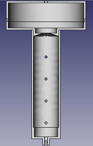
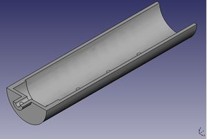
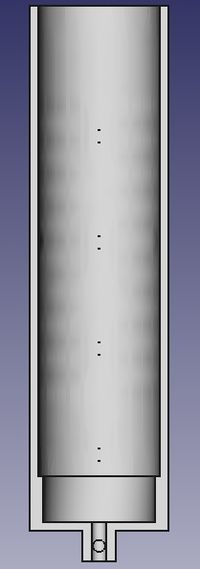
Prototype 1 will be designed to be a small scale reactor that contains only core components of a reactor chamber, reduction chamber, gas fluidization and recycle system, substrate mixing system and temperature controls. The reactor is 20 cm internal diameter with a reaction zone of 1.4 meters. The reactor is made of single piece of material to which a distributor plate is attached and it may be possible to alter the reaction zone by changing the height of the distributor plate and amount of catalyst. The reduction zone is designed to made of two pieces for easy manufacture and assembly and will have dimensions of 30 cm tall and 60 cm in diameter. The reactor will be assembled in a reinforced frame which will be mounted to the floor. Depending on the reaction parameters the reactor may be made from stainless steel, however more temperature robust reactors will be made of a material that is able to withstand high heat such as silicon carbide or a ceramic material. A firebrick jacket will be built around the machine with a small air gap between the two and serve as a thermal block and for physical containment. | Prototype 1 will be designed to be a small scale reactor that contains only core components of a reactor chamber, reduction chamber, gas fluidization and recycle system, substrate mixing system and temperature controls. The reactor is 20 cm internal diameter with a reaction zone of 1.4 meters. The reactor is made of single piece of material to which a distributor plate is attached and it may be possible to alter the reaction zone by changing the height of the distributor plate and amount of catalyst. The reduction zone is designed to made of two pieces for easy manufacture and assembly and will have dimensions of 30 cm tall and 60 cm in diameter. The reactor will be assembled in a reinforced frame which will be mounted to the floor. Depending on the reaction parameters the reactor may be made from stainless steel, however more temperature robust reactors will be made of a material that is able to withstand high heat such as silicon carbide or a ceramic material. A firebrick jacket will be built around the machine with a small air gap between the two and serve as a thermal block and for physical containment. | ||
The gas input will be attached to the lowest point of the reactor and substrate inputs will be located slightly above. The reactor will be designed to prevent any solid formations or fouling a main technical problem in current industry. The distributor plate will be attached to a lip located 15 cm above the input zone and attachments to raise the distributor shouldn't be difficult to incorporate. A series of screw-in ports in the reactor zone will allow additions and removal reagents and a design that allows the passage of gas, liquid, and solid phase material should be a goal. To minimize thermal losses and increase efficiency it is proposed that the substrate hopper, catalyst hopper and gas input be clustered in a thermal mass that will be maintained at the same temperature | The gas input will be attached to the lowest point of the reactor and substrate inputs will be located slightly above. The reactor will be designed to prevent any solid formations or fouling a main technical problem in current industry. The distributor plate will be attached to a lip located 15 cm above the input zone and attachments to raise the distributor shouldn't be difficult to incorporate. A series of screw-in ports in the reactor zone will allow additions and removal reagents and a design that allows the passage of gas, liquid, and solid phase material should be a goal. To minimize thermal losses and increase efficiency it is proposed that the substrate hopper, catalyst hopper and gas input be clustered in a thermal mass that will be maintained at the same temperature. As detailed in US patent 4234752 passing the dehydration products through chambers of decreasing temperature (e.g. 50 C, 0 C, -70 C) is effective at removing water and unreacted alcohol from the product stream and this method of purification is suggested for prototype 1. | ||
The reactor will be in conformity to the OSE design standards and allow for easy manufacture, assembly, and reconfiguration. Beyond the reactor and reduction chamber which will be produced on-site off the shelf gas analyzers, gas flow controllers, gas compressor and various other components will be utilized. In order for the reactor to be able to control both the dehydration and polymerization reactions it must be able to control exothermic and endothermic reactions. Prior art has found that reactor chambers usually are adiabatic and temperature control should be incorporated into the gas stream; so heat must be removed from the product stream in exothermic reactions and added to the input streams in endothermic reactions. | The reactor will be in conformity to the OSE design standards and allow for easy manufacture, assembly, and reconfiguration. Beyond the reactor and reduction chamber which will be produced on-site off the shelf gas analyzers, gas flow controllers, gas compressor and various other components will be utilized. In order for the reactor to be able to control both the dehydration and polymerization reactions it must be able to control exothermic and endothermic reactions. Prior art has found that reactor chambers usually are adiabatic and temperature control should be incorporated into the gas stream; so heat must be removed from the product stream in exothermic reactions and added to the input streams in endothermic reactions. | ||
Revision as of 19:26, 14 April 2012
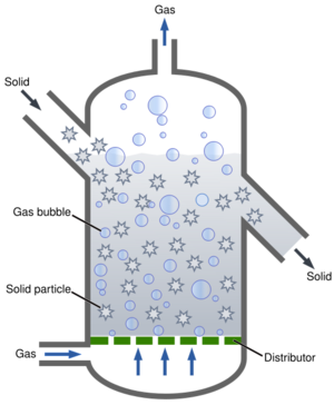
Fluidized bed reactor (FBR) are chambers that allow the mixing of liquid or gas substrates with powdered catalysts such that the catalyst acts like a fluid, maximizing mixing and catalyst action. The basic configuration is detailed to the right where a substrate is passed upward through the chamber under pressure through a plate that supports the catalyst. FBRs are essential production of many materials and chemicals and is needed for several basic capabilities of the GVCS.
FBR for bioplastic production
As part of the OSE product ecology a reactor that could be used for ethanol dehydration and ethylene polymerization is a proposed route to locally produced renewable bioplastic. Due to the nature of the subtrates, powdered catalysts, and optimal catalytic conditions FBRs have demonstrate superior performance with high process reactivity and selectivity.
Defining the machine requirements:
1. Reactor chamber with ability to add or remove substrate, product, catalyst, gases, and control temperature, pressure, and the speed which substrate moves through the reactor. a. Dimensions based on reaction volume? b. Hoppers would have to be of adequate size to benefit reaction volume
2. Safety: able to withstand heat and pressure, dangerous chemicals kept behind two layers of protection, product handled with precautions a. reactor materials b. design for longterm quality
3. Recycling of unused substrate, carrier gas, catalyst. a. Catalyst regenerator to autoclave and activate used up catalyst.
4. Saving thermal energy: isothermal or adiabatic, heat catalyst and substrate with steam depending on moisture requirements
5. Control of atmosphere: gas content, increased and decreased pressure ranges, gas content in the reactor and downstream, gas mixture controls upstream
6. Control and interface: sensors of pertinent conditions and an easy to understand display of the conditions, controls over conditions and inputs and outputs
Collect user stories to decide upon most important features to incorporate into first prototype.
SEBD components: 2 processes: dehydration and polymerization 1. Reactor 2. Reduction zone Gas input and makeup 3. Gas hookup for main port, substrate and catalyst. 4. Gas flow controller for main port and possibly substrate and catalyst. Pressure sensor and control. Gas recycle and gaseous product collection 5. Gas analyzer 6. Gas and liquid phase separation. 7. Gas product separation for ethylene via gas fractionation column or gas scrubber gas recycle without gaseous production. 8. Compressor and heat removal from exothermic processes. 9. Gas recycle to main gas port. Substrate control 10. Vaporization of liquid ethanol and passage through substrate port. 11. Control of input of gaseous ethylene substrate. Product removal Catalyst maintenance, loading, removal, and regeneration. Control unit
Literature and patent review
Production of Polyethylene Using Gas Fluidized Bed Reactor written by Tham Chee Mun reviews the industrial processes that have been employed and are currently used. The history of industrial polyethylene processes including reactor design and catalyst evolution, differences in polyethylene fibers, mathematical modeling of the polymerization reaction, and recommendations for operation are covered. Early processes were for the production of low density polyethylene and required high pressures in the order of 3000 atm and elevated temperatures, and this process is still used in the production of polyethylene vinyl acetate. Newer catalysts can produce higher density fibers at lower temperature and pressure and should be simplified and bootstrapped for OSE. Further refinements to the technique included starting the reactor with prepolymers, reconfiguration of the gas recycle line to conserve heat and reduce fouling, and pretreatment of the substrate and catalyst. Modeling of the reaction process incorporates the total possible reactions and their probability. A recommendation that OSE should consider while developing lines of plastics is the loss of transition material and a production process that cycles through similar plastics to minimize wasted material.
Industry equipment often follows the dimensional guidelines of reactor bed height to width ratio of 6-7.5 and a reduction zone with a ratio 1:2 is connected to the top of the reactor with a sloping section that assists in separating catalyst and polymer from recycle gas. The reactor bed is usually kept at a pressure of 0.07 atm (1 psi). http://klmtechgroup.com/PDF/Articles/Fluidized-Bed-Reactor.pdf
US patent 4,003,712 issued to Miller on Jan. 18, 1977 details a fluid bed reactor for use in a olefin polymerization.
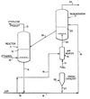
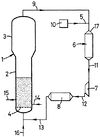
The reactor contains a reaction zone 12 where substrate and catalyst are combined. The substrate is supported by a fluid bed which allows the injection of substrate which allows maximum mixing due to the fluid like behavior of the catalyst. Unused substrate, catalyst, and carrier gas can be recycled through the system. Above the reaction zone is a slow down zone 14 where products collect and are sorted. Gas collects the velocity reduction zone and recycle gas is collected through the a line at the top of the zone. An optional cyclone 22 can aid in gas collection and a filter 24 catches small particles. A heat exchanger 26 acts to recycle heat and maintain the system at a constant temperature and the gas is compressed by a compressor 28. New catalyst can be added through input 30 with a proper gas mixture and preheated, reserve catalyst is held in nitrogen in 32.
A reactor device detailed in U.S. patent 4,134,926 belonging to Tsao and Zasloff issued Jan 6 1979 utilizes a fluid bed reactor (11) to catalyzed the reaction of ethanol dehydration.
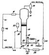
The reactor contains powdered catalyst supported on a distributor which can dispense feed ethanol through the catalyst. Ethanol is passed through the distributor in gas phase at 750 C into the reactor chamber at the same temperature. The catalyzed reaction takes place on the surface of the catalyst powder, and the product escapes as gas. The product is equal parts water and ethylene. Catalyst may be removed and loaded into reactor using hopper chambers, which offer the advantage of preparing the new catalyst to ideal temperature and conditions increasing control of the main reactors conditions. According to the patent ethylene yields of 99% are possible with fluidized bed reactors.
US patent 4,383,095 issued to Goeke on May 10 1983 details a high activity catalyst and a the operation of the fluid bed reactor for its use. The FBR adds activator compounds at the hottest point of the gas recycle line which would be downstream of the compressor and before the heat exchanger?, however the patent calls for placement downstream of the heat exchanger.
US patent 5,028,670 issued to Chinhe and Dumain on July 1, 1991 details a fluid bed reactor configured for olefin polymerization so as to avoid fouling by particles carried into the gas recycle line.
A liquid vapor separation The device utilizes two heat exchangers in the gas recycle line downstream.
http://conservancy.umn.edu/bitstream/104626/1/Skinner_Michael_April2011.pdf
Proposed plan of action
1. Construction of simple small (laboratory) scale reactor that may or may not incorporate ability to remove and reload catalyst or recycle gases.
2. Demonstration of reactors capabilities to catalyze ethanol dehydration and ethylene polymerization using purchased catalysts and substrates. Successful creation of polyethylene will demonstrate the ability to conduct the process on a small scale.
3. Construction of second generation reactor that incorporates more advanced loading and unloading abilities and environmental controls that can operate in continuous mode.
4. Testing of reactor and utilization in other catalyst reactions under different conditions than bioplastic reactions.
5. Construction of full scale reactor capable of supporting village sized population with ability to load multiple substrates, catalyst hopper, gas control and recycling, and which can be operated in extended continuous for long periods and rapidly reconfigured.
6. Demonstration of industrial standard open source fluid bed reactor in a variety of applications.
Prototype 1
Prototype 1 will be designed to be a small scale reactor that contains only core components of a reactor chamber, reduction chamber, gas fluidization and recycle system, substrate mixing system and temperature controls. The reactor is 20 cm internal diameter with a reaction zone of 1.4 meters. The reactor is made of single piece of material to which a distributor plate is attached and it may be possible to alter the reaction zone by changing the height of the distributor plate and amount of catalyst. The reduction zone is designed to made of two pieces for easy manufacture and assembly and will have dimensions of 30 cm tall and 60 cm in diameter. The reactor will be assembled in a reinforced frame which will be mounted to the floor. Depending on the reaction parameters the reactor may be made from stainless steel, however more temperature robust reactors will be made of a material that is able to withstand high heat such as silicon carbide or a ceramic material. A firebrick jacket will be built around the machine with a small air gap between the two and serve as a thermal block and for physical containment.
The gas input will be attached to the lowest point of the reactor and substrate inputs will be located slightly above. The reactor will be designed to prevent any solid formations or fouling a main technical problem in current industry. The distributor plate will be attached to a lip located 15 cm above the input zone and attachments to raise the distributor shouldn't be difficult to incorporate. A series of screw-in ports in the reactor zone will allow additions and removal reagents and a design that allows the passage of gas, liquid, and solid phase material should be a goal. To minimize thermal losses and increase efficiency it is proposed that the substrate hopper, catalyst hopper and gas input be clustered in a thermal mass that will be maintained at the same temperature. As detailed in US patent 4234752 passing the dehydration products through chambers of decreasing temperature (e.g. 50 C, 0 C, -70 C) is effective at removing water and unreacted alcohol from the product stream and this method of purification is suggested for prototype 1.
The reactor will be in conformity to the OSE design standards and allow for easy manufacture, assembly, and reconfiguration. Beyond the reactor and reduction chamber which will be produced on-site off the shelf gas analyzers, gas flow controllers, gas compressor and various other components will be utilized. In order for the reactor to be able to control both the dehydration and polymerization reactions it must be able to control exothermic and endothermic reactions. Prior art has found that reactor chambers usually are adiabatic and temperature control should be incorporated into the gas stream; so heat must be removed from the product stream in exothermic reactions and added to the input streams in endothermic reactions.
Steps in operation of FBR : 1. Establish steady state reactor pressure and temperature conditions with catalyst in chamber. 2. Pass substrate into reaction chamber and move through catalyst for optimal length of time. 3. Collection of product from gas stream or from reaction zone. 4. Collection of flow through gas from reduction zone. 5. Preparation of gas for recycle. 6. Gas recycle through main gas port.
Links
http://en.wikipedia.org/wiki/Fluidized_bed_reactor
http://www.fischer-tropsch.org/Bureau_of_Mines/ri/ri_6209/ri_6209.pdf
