Fluidized Bed Reactor
| Fluidized Bed Reactor | ||
|---|---|---|
| Home | Research & Development | Bill of Materials | Manufacturing Instructions | User's Manual | User Reviews | File:Fluidized Bed Reactor.png | |
Basics
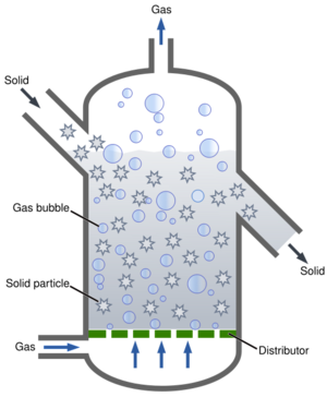
Fluidized bed reactors (FBR) are chambers that allow the mixing of liquid or gas substrates with powdered catalysts such that the catalyst acts like a fluid, maximizing mixing and interaction. The basic configuration is detailed to the right where a substrate is passed upward into the chamber under pressure through a plate that supports the catalyst. FBRs are essential for the production of many materials and chemicals, and could be an effective tool for several basic capabilities of the GVCS.
An OSE FBR should be built of discrete components that are integrated rather than dependent on one another, so a machine can be assembled into configurations for applications that use different pieces of equipment. This approach is also necessary for scrum and decentralized development by breaking down this complex machine into self-evident pieces. As a complex machine it will also be useful to develop components that are involved in a common task or reaction parameter as part of a subsystem, an example would be thermal flow controllers that control injection of substrate and vacuum pumps that remove products. Components of subsystems should be designed to control a specific parameter in the most flexible way possible while being under the control of a system controller (computer) that integrates the system components into a cohesive action. This will allow component actions in the form of programs to be distributed and replicated. Much of this is already industry standard practice.
The reactor chamber itself will have no active role and will simply be a container that can be connected to different input and output lines, and is optimized for mixing of components and maintenance of optimal reaction conditions. Use of an external frame seems to be fairly standard in industry and would allow separate mixing, reaction, and velocity reduction zones to be simply, and securely combined. FBRs could be a versatile platform for many OSE natural resource and chemical engineering ecologies. The reactor core will be designed so that it can be used without modification in a wide variety of applications through reconfiguration of the components. As OSE identifies chemical processes that should be conducted in a fluid bed reactor a thorough open source literature review should be conducted within this page and necessary subsystems and components identified.
Potential Applications
- Chemical Reactors
- Liquid/Gas Scrubbers (Mainly with Activated Carbon but some catalyst coated Zeolite would work as well)
- Be adapted to/from Fluidized Bed Combustors and/or Fluidized Bed Gassifiers
- Improve PBRs and Bioreactors via a fluidized substrate
- Or for better WWT Sluge Formation
Types of fluidized bed reactors
Bubbling fluid reactor - reactor where powder catalyst rate of settling is balanced with an the velocity of the upward gas; the gas input is located at the bottom center of the mixing zone
Circulating fluid reactor - reactor where the powder catalyst settling rate is higher than the velocity of the input gas; gas input is located on the side of the reactor and the catalyst is supported underneath
Transport reactor - reactor where powder catalyst rate of settling is lower than the velocity of the input gas; a cyclone or downdraft reactor is incorporated into the initial gas escape to capture entrained dust
Status Brief
A modular multi-use OSE reactor is currently in the research and development phase. The reactor is proposed to be able to operate in multiple states including fluid, melt, and solid. Bioplastic production (specifically polylactic acid and polyethylene see below) are first proposed applications, followed by expansion of chemical engineering process applications. Defining the reactor specifications and subsystems for bioplastic production is below. Analysis of industry standard equipment is underway but off-shelf components do not appear to be up to specifications.
Areas of blockage: Info/design of a temperature control jacket for high and low temp applications, info/design of sensors (temperature, pressure, gas analysis) and placement in the proposed system configurations, subject matter expertise on fluid dynamics of system (pressure/gas flow needed to maintain fluidization and maintain desired substrate and catalyst interaction times), distributor plate design.
Documentation Brief
A review of publicly available information on FBR designs is underway on the research and development page. Reviews of polylactic acid reactor configurations is needed. Extensive research on subsystems is still needed before specifications can be defined and designs proposed.
FBR for bioplastic production
A variety of bioplastics are currently being produced including polycarbonate, polylactic acids, and polyethylene. Polyethylene is the most produced plastic in the world and can be made in high and low density forms based upon branching. A reactor that could be used for ethanol dehydration and ethylene polymerization is a proposed route to locally produced renewable bioplastic. Due to the nature of the subtrates, powdered catalysts, and optimal catalytic conditions FBRs have demonstrated superior performance in the both steps of the ethanol to polyethylene process, with high reactivity and selectivity. An OSE FBR could fulfill the specific need for synthesis of bioplastics and by being built along OSE guidelines could be configured for a variety of chemical engineering applications.
Polyethylene from ethanol process
A complete production route from renewable feedstocks is under current review at Polyethylene from Ethanol. See Status Brief for current development of the project and areas of blockage.
Defining the bioplastic FBR requirements
1. Reactor chamber with ability to add or remove substrate, product, catalyst, gases, and withstand temperature, pressure, and the speed which substrate moves through the reactor. a. Dimensions based on reaction volume and contact time between substrate and catalyst
2. Safety: able to withstand heat and pressure, dangerous chemicals kept behind two layers of protection, product handled with precautions a. reactor materials b. design for longterm quality
3. Recycling of unused substrate, carrier gas, catalyst. a. Catalyst regenerator to autoclave and activate used up catalyst.
4. Saving thermal energy: isothermal or adiabatic, heat catalyst and substrate with steam depending on moisture requirements
5. Control of atmosphere: gas content, increased and decreased pressure ranges, gas content in the reactor and downstream, gas mixture controls upstream
6. Control and interface: sensors of pertinent conditions and an easy to understand display of the conditions, controls over conditions and inputs and outputs
Collect user stories to decide upon most important features to incorporate into first prototype
SEBD components:
2 processes: dehydration and polymerization
1. Reactor
2. Reduction zone
Gas input and makeup
3. Gas hookup for main port, substrate and catalyst.
4. Gas flow controller for main port and possibly substrate and catalyst. Pressure sensor and control.
Gas recycle and gaseous product collection
5. Gas analyzer
6. Gas and liquid phase separation.
7. Gas product separation for ethylene via gas fractionation column or gas scrubber gas recycle without gaseous production.
8. Compressor and heat removal from exothermic processes.
9. Gas recycle to main gas port.
Substrate control
10. Vaporization of liquid ethanol and passage through substrate port.
11. Control of input of gaseous ethylene substrate.
12. Product removal
Catalyst control
Catalyst maintenance, loading, removal, and regeneration.
User interface
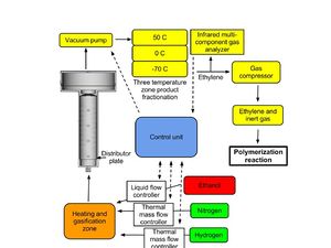
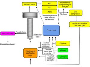
Control unit - integration of reactor sensors with current status of thermal mass flow controller, liquid mass flow controller, gas analyzer, hopper temperature controllers, and a method for programming and automating processes.
Proposed plan of action
1. Construction of simple small (laboratory) scale reactor that may or may not incorporate ability to remove and reload catalyst or recycle gases.
2. Demonstration of reactors capabilities to catalyze ethanol dehydration and ethylene polymerization using purchased catalysts and substrates. Successful creation of polyethylene will demonstrate the ability to conduct the process on a small scale.
3. Construction of second generation reactor that incorporates more advanced loading and unloading abilities and environmental controls that can operate in continuous mode.
4. Testing of reactor and for high purity ethylene production and polyethylene polymerization. Refinement of operation and production of second generation bioplastic polyethylene vinyl acetate for use in greenhouse glazing.
5. Construction of full scale reactor capable of supporting village sized population with ability to load multiple substrates, catalyst hopper, gas control and recycling, and which can be operated in extended continuous for long periods and is rapidly reconfigured.
6. Demonstration of industrial standard open source fluid bed reactor in a variety of applications.
7. Material abundance from local feedstocks and catalysts.
Subsystems and components breakdown: 1. Reactor core 2. Gas loop 3. Substrate loader 4. Catalyst loader
Steps in operation of FBR : 1. Establish steady state reactor pressure and temperature conditions with catalyst in chamber. 2. Pass substrate into reaction chamber and move through catalyst for optimal length of time. 3. Collection of product from gas stream or from reaction zone. 4. Collection of flow through gas from reduction zone. 5. Preparation of gas for recycle. 6. Gas recycle through main gas port.
Prototype 1
Specifications
Dimensions will be altered after fillets are added to
- Flowrate - 0.5 - 5.0 m/s
- Pressure - -50 psi - 500~600 psi
- Temperature - 0 - 500~600 C
- Input gas port with side ports
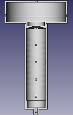
- Mixing zone dimensions - 2 cm radius x 15 cm depth
- volume - 188.4 ml
- Reaction zone dimensions - 3 cm radius x 40 cm depth
- Reaction zone volume - 1.113 l
- Reduction zone entrance dimensions - 2.5 cm to 1.25 cm radius x 15 cm depth
- Reduction zone dimensions - 60 cm radius x 30 cm depth (?are these good dimensions to prevent fouling)
- Reduction zone volume - 339.120 l
- Outlet port(s) offset from center.
- Materials - Nonreactive stainless steel
Reactor Core
Prototype 1 will be designed to be a small scale reactor that contains only core components of a reactor chamber, reduction chamber, gas fluidization, substrate mixing system, and temperature, pressure and flowrate controls connected to a control unit. The prototype reactor is designed to be bubbling fluid reactor which has been found to be ideal for the designated processes. The reactor is 6 cm internal diameter with a reaction zone of 40 cm. The reactor is made of single piece of material to which a distributor plate is attached and it may be possible to alter the reaction zone by changing the height of the distributor plate and amount of catalyst. The reduction zone is designed to made of two pieces for easy manufacture and assembly and will have dimensions of 30 cm tall and 30 cm in diameter. The reactor will be assembled in a reinforced frame which will be mounted to the floor. Depending on the reaction parameters the reactor may be made from stainless steel, however more temperature robust reactors will be made of a material that is able to withstand high heat such as silicon carbide or a ceramic material. A firebrick jacket will be built around the machine with a small air gap between the two and serve as a thermal block and for physical containment.
The reactor will be in conformity to the OSE design standards and allow for easy manufacture, assembly, and reconfiguration. Beyond the reactor and reduction chamber which will be produced on-site off the shelf gas analyzers, gas flow controllers, gas compressor and various other components will be utilized. In order for the reactor to be able to control both the dehydration and polymerization reactions it must be able to control exothermic and endothermic reactions. Prior art has found that reactor chambers usually are adiabatic and temperature control should be incorporated into the gas stream; heat must be removed from the product stream in exothermic reactions and added to the input streams in endothermic reactions.
Used reactors of all sizes and for many different applications are for sale at LabX or Kitmondo if a cheap industry standard reactor needs to be acquired first for standards examination.
Configuration
The gas input will be attached to the lowest point of the reactor and substrate inputs will be located slightly above. The reactor will be designed to prevent any solid formations or fouling a main technical problem in current industry. The distributor plate will be attached to a lip located 15 cm above the input zone and attachments to raise the distributor shouldn't be difficult to incorporate. A series of screw-in ports in the reactor zone will allow additions and removal reagents and a design that allows the passage of gas, liquid, and solid phase material should be a goal. To minimize thermal losses and increase efficiency it is proposed that the substrate hopper, catalyst hopper and gas input be clustered in a thermal mass that will be maintained at the same temperature. As detailed in US patent 4234752 passing the dehydration products through chambers of decreasing temperature (e.g. 50 C, 0 C, -70 C) is effective at removing water and unreacted alcohol from the product stream and this method of purification is suggested for prototype 1.
Distributor Plate
User:Eric 's bit
- Been doing some looking into fluidized beds, this seems to be the hardest to find componet
- Seems to be some sort of sintered material most often
- Fish tank "air stones" may work small scale, but are often:
- Too small
- Wrong Shape
- Not heat tolerant
- Graphite/charcoal may work; applied science did this for an Air Bearing
- Combustible, but this may only be an issue in combustor/gassifier designs?
- Also will enough air pass through?
- All in all this needs either someone who is good at navigating the more "industrial" type of suppliers, as that is all i seemed to find for these?
- Also some fiddling around by someone who has a shop to see what diy options exist etc
EP: A perforated plate design would be the simplest. https://www.semanticscholar.org/paper/THE-INFLUENCE-OF-DISTRIBUTOR-DESIGN-ON-FLUIDIZED-Wormsbecker-Pugsley/3bfb18e7a2242f3aeeb03991648be9f080c165b0/figure/1 A piece of metal with a diameter to match the inner diameter of the reactor, with holes drilled through it. The reactor would have a narrower section at the bottom and the plate would sit on the lip. The plate would be screwed into the lip, or a screw could pass horizontally through the reactor and the plate would have a cut out to pass through and would be rotated to be held down.
Mass flow controllers
Thermal mass flow controllers seem to be the preferred way to measure gas inputs and outputs and can be found commercially for a few thousand dollars. Alternatively, arduino based thermal mass flow controller using a IST FS5 thermal mass flow sensor have been built by hobbyists. An overview of the design and components of a mass flow controllers can be found here http://www.advanced-energy.com/upload/File/White_Papers/SL-MFCFUND-270-01.pdf. Alicat Scientific sells a variety of products http://www.alicatscientific.com/products.php for the measuring and control of flow, pressure and temperature. Gas flow controllers that are factory configured to handle ethylene, nitrogen, and hydrogen and can be connected to a computer or arduino through a serial port.
Boiler mixer chamber
A chamber for the mixing, heating and changing to gas phase of substrates will be located downstream of the flow controllers for the feed lines. A bubbling gas configuration is a simple and tested configuration for inputs with a side port for introducing liquid ethanol and bottom side ports for introducing gas. Heat is provided by a heat jacket and a heat coil from the jacket to the chamber bottom.
http://www.google.com/patents?id=9qRkAAAAEBAJ
http://www.google.com/patents?id=a_klAAAAEBAJ
http://www.bronkhorst.com/files/published_articles/liquid.pdf
Gas product measurement
Ethylene is detected spectroscopically through non-dispersive-infrared (NDIR) which can be used to detect other gases too. There are a few strategies that could be employed depending on a balance of expensive equipment with high accuracy, lower cost less accurate equipment, or low cost positive identification through chemical means. The Xendos 2550 is a multicomponent gas analyzer cited for its use in laboratory scale reactors and can quantify ethylene, CO2, CO, and other contaminants http://www.sanwell-tech.com/webEdit/UploadFile/2009920173050784.pdf. User Manual
http://www.yokogawa.com/rd/pdf/TR/rd-te-r05302-013.pdf
http://www.gasalarm.co.in/datasheets/Ethylene-ndir-leakage-concentration-monitoring-sensor.pdf
http://www.google.com/patents?id=aWU8AAAAEBAJ
http://www.google.hu/patents/US5055688
http://www.seas.columbia.edu/earth/wtert/sofos/nawtec/nawtec12/nawtec12-2230.pdf
Product purification
Separation of ethylene from unreacted substrate and water is will initially be through condensation zones of decreasing temperature. It may not be necessary to remove inert gas from the product stream if it won't interfere with polymerization as long as its content can be quantified. The quantity of inert gas must be low enough that further inert gas can be incorporated during the polymerization step as the means of mixing.
A gas compressor will be attached to the lowest temperature zone and will compress the ethylene gas product.
Controller
The most viable short term option to demonstrate a programmable FBR would be with Alicat sensors and their software program Flow Control. Open source sensors can be developed with arduino chips but for a first prototype these off the shelf components seem to be the easiest to integrate.
Reactor for polylactic acid vacuum dehydration
A reactor configured for polylactic acid dehydration will use a reactor core that can maintain a near vacuum (0.5 torres) and can be heated to 200 C. The melt\solid state would be disturbed by gas flow and heat must be added through a heat jacket either configured for hot oil, steam, or electric heating. The bottom port will be sealed with a screw in end cap with high heat O-ring and a sealing grease if temperature allows. The reaction zone will not be constrained by a distributor plate.
Polylactic acid due to multi-step polymerization process would be conducted in a batch fashion and all reagents would be placed in the reactor before starting.
Heat Jacket
An insulating temperature controlling jacket would expand the configurations possible with the chemical engineering tools to allow active heating and cooling directly to a reaction (making the process isothermal) as is necessary for high quality polylactic acid polymerization. A heat jacket contains a heating element either by conduction (oil or steam) or electric but fluid temperature control offer the advantage of removing heat using a lower temperature fluid.
An OSE temperature control jacket could use a simplified heat exchanger design to create a spiral of tubes that can be insulated in a metal shell. The jacket should be design to be easily integrated with the reactor by placing the reactor in the jacket and mounting the components to the frame. In this way modularity is maintained while integrating a new temperature control element.
Reactor Lid
A reactor lid will be necessary and replace the velocity reduction zone. A reactor lid can be as simple as a fitted flat top capable of forming a seal and with a port for establishing a vacuum or can incorporate more ports for substrate inputs and sensors.
Condenser
A reflux condenser removes moisture from the product stream which is necessary to prevent fouling of the vacuum pump. Condensers use a lower temperature to cause gases to enter liquid phase and collect the liquid. A Dean-Stark apparatus is a form of condenser that is commonly used, it is h shaped with the right side connected to the reaction and the a collecting chamber connected to the bottom left.
Vacuum Pump
A vacuum pump is necessary to drive polymerization by removing water as a gas.
BOM
PLA reactor log
Tue Apr 14, 2020
EP:
I think the industry standard depends a lot upon the scale of the reactor but it is basically a pipe (big or small). Hypothetically a capped up plumbing pipe could work for PLA. The material is preferably stainless steel, though certain reactants may be better in a different material reactor.
PLA doesn't need an input gas from my understanding. My thinking was to use the same body for all of the reactors, though with progressively more ports for additional capabilities. Bottom port for input gas and a gas distributor plate to make it a fluidized bed reactor, side ports to inject additional reactants/catalysts or remove product.
The reactor body could be configured for different functions. For PLA the other modules would be heating, vacuum, lid, condenser (in addition to the reactor body). It did seem like the simpler setup. A controller wouldn't be necessary if temperature and vacuum were manually monitored, though vacuum and temperature sensors would likely be desired (likely accommodated by the lid).
MJ sez:
Any thoughts on low pressure sensor for vacuum pressure? ' The florida project showed a good candidate for pressure sensor at the breath pressure - University_of_Florida_Ventilator - but that would be too high for vacuum.
EP:
I don't know much about the sensors but there seems to be several types. I envisioned using chemical engineering sensors that screw into a port and have an external connector (just a random company). The other option would be to mount a pressure gauge for manual reading, there should be temperature gauges too (I kinda like that idea if there is no controller and things are barebones).
Do you have an idea on how to maintain the vacuum at a relatively constant level with the vacuum pump? Maybe some vacuum pumps come with an internal sensor or mechanism to maintain a set pressure. At work we filter media, so they hooked up the pumps to an arduino that powers it up every 2 minutes or so. If a sensor were incorporated maybe pressure could be regulated.
Links
http://www.make-biodiesel.org/Processors/joe-streets-vacuum-processor-plans.html
FBR for iron production
The design detailed above is largely for the production of bioplasics. With major design modifications, an FBR could be devised for the reduction of iron oxide to metallic iron. The process is described on the Direct_Reduced_Iron_(DRI) page. As the reducing gas, one would feed either syngas or methane into the bottom of the FBR. Iron oxide, possibly extracted from subsoil, sand or river sediments by magnetic sorting, would go in at the top left. Exiting gas will be a mixture of CO2, CO and H2. Out comes hot reduced iron. If exposed to air, this hot powder would immediately be re-oxidized. Therefore, it should be put in an induction Furnace right away, while still hot.
Literature and patents for review
http://lup.lub.lu.se/luur/download?func=downloadFile&recordOId=786321&fileOId=786858
http://www.jstage.jst.go.jp/article/isijinternational/45/2/151/_pdf
http://www.fischer-tropsch.org/Bureau_of_Mines/ri/ri_6209/ri_6209.pdf
http://www.google.com/patents?id=ZQcwAAAAEBAJ
http://www.google.com/patents?id=TFwsAAAAEBAJ
http://www.google.com/patents?id=BUM3AAAAEBAJ
http://www.google.com/patents?id=9VkdAAAAEBAJ
http://www.google.com/patents?id=4UQfAAAAEBAJ
http://www.google.com/patents?id=pxonAAAAEBAJ
FBR for biomass pyrolysis
FBRs have been been studied for their effectiveness in biomass pyrolysis applications and have been found to be effective at controlling the gas and liquid phase processes. A typical configuration of a FBR for pyrolysis is shown with simplified components at http://www.pyne.co.uk/Resources/user/Bubbling%20fluid%20bed.bmp. Pyrolysis as a degradative process can yield a variety of products which are characterized generally as gas and liquid combustibles and solid char. Fast pyrolysis yields a high fraction of oily liquid products, while gasification yields gaseous products. Pyrolysis in an FBR will primarily be for the production of chemicals or liquid components as the Gasifier Burner seems to be a more appropriate technology for conversion of biomass to combustible gas for heating.
Internal Links
External Links
Literature and patents for review
http://www.mdpi.com/1422-0067/9/9/1665/pdf
http://csp.eworlding.com/3r/congress/manu_pdf/328.pdf
http://www.nh.gov/oep/programs/energy/documents/biooil-nrel.pdf
http://www.google.com/patents?id=cWQ6AAAAEBAJ
http://www.google.com/patents?id=rI8eAAAAEBAJ
http://www.google.com/patents?id=egojAAAAEBAJ
http://www.google.com/patents?id=auM3AAAAEBAJ


